Could it be that MUTE is activated?
It isn't mute. A tiny bit of sound comes through... I guess I have to check if i made any additional damage when breaking the notorious pin 16
")
As for the datasheet, will check!
MUTE means important damping of the signal, not complete removal of the signal. If the reduced sound level is the same for both channels it may very well mean the MUTE pin is activated.
There's inly one channel...?
It seems that since increasing the carrier frequency, the noise level of the minidsp went significantly down and now the damn thing is almost perfectly quiet. Is it possible that the amps radiated noise to the minidsp when operating at 120khz?
When the frequency is too low, the choke cores approach saturation or even saturates and the current spikes become high. High current spikes may cause increased noise in the PCB tracks and increased radiation of noise.
Yes, it is possible. At least, it now seems to work.
I guess it is a foil capacitor to replace one of the small ceramic SMD capacitor used at the inputs (signal coupling capacitors).There's no way these will fit
True, no chance to get it in place. You can find smaller but they will still be too large.
Now I'm confused... I kind of thought the grey caps by the inductors on the pcb are part of the filter. True, never checked anything...
Aren't they?
The big new ones are polypropylene caps for the LC filter - replacement for the grey ones.
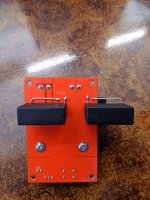
I thought that in the worst case, I could mount the inductors so that they lay on their sides, and the caps on the bottom of the pcb. Or just leave the legs unsightly long and let the caps protrude from the pcb several cm.
Aren't they?
The big new ones are polypropylene caps for the LC filter - replacement for the grey ones.
I thought that in the worst case, I could mount the inductors so that they lay on their sides, and the caps on the bottom of the pcb. Or just leave the legs unsightly long and let the caps protrude from the pcb several cm.
Sorry, I misunderstood. The smaller gray (foil) capacitors on the board are indeed part of the output filter. I did not know that you want to replace those. Yes, the bigger ones you bought may be a little better but the improvement will be marginal.
If I make a better output filter, which is often bigger in size, I tend to move the components to a separate board very close to the output part of the amplifier board.
If I make a better output filter, which is often bigger in size, I tend to move the components to a separate board very close to the output part of the amplifier board.
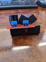
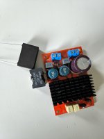
Did the soldering today, and it came out like this...
Looks stupid and badass at the same time
Hope those long leads won't cause any problems.
try it !
look before and check if some solder joints etc are not happend and measure with DMM if you do not get shorts.
chris
FauxFrench, is that decoupling capacitor board one you would recommend? How would you modify it for single rail DC?
Carte filtrante de redresseur d'amplificateur de Lusya double Module d'alimentation Audio de cc avec le B8 001 fini de capacite-in Amplificateur from Electronique on Aliexpress.com | Alibaba Group
Carte filtrante de redresseur d'amplificateur de Lusya double Module d'alimentation Audio de cc avec le B8 001 fini de capacite-in Amplificateur from Electronique on Aliexpress.com | Alibaba Group
FauxFrench, is that decoupling capacitor board one you would recommend? How would you modify it for single rail DC?
Carte filtrante de redresseur d'amplificateur de Lusya double Module d'alimentation Audio de cc avec le B8 001 fini de capacite-in Amplificateur from Electronique on Aliexpress.com | Alibaba Group
I have ths one. No need for modding, or I don't understand exactly
FauxFrench, is that decoupling capacitor board one you would recommend? How would you modify it for single rail DC?
Carte filtrante de redresseur d'amplificateur de Lusya double Module d'alimentation Audio de cc avec le B8 001 fini de capacite-in Amplificateur from Electronique on Aliexpress.com | Alibaba Group
Hi Graham,
I have that board. Connect the input DC source "+" to one of the input AC terminals and "-" to input GND. Use the output "+" and output GND ("-") terminals.
This way you use only one of the capacitors (10000uF) unless you modify the board.
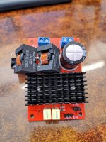
Ok, old peasant stock boards are out, and new, upgraded, beefy ones (with output filter a few times more expensive than the amp itself) are in.
Let me say I changed one channel first, and then the other, hoping I could hear a difference. of the mod..
I guess I could use audiophool vocabulary to describe the sound now, but the simple and most honest thing to say right now is: I don't think there is any real difference.
Meaning the humble Chinese amp board (with corrected carrier freq.) is a damn spectacular product.
Modded looks cooler, though.
Hi Graham,
I have that board. Connect the input DC source "+" to one of the input AC terminals and "-" to input GND. Use the output "+" and output GND ("-") terminals.
This way you use only one of the capacitors (10000uF) unless you modify the board.
I have + and - connected to both AC terminals, not AC and GND. Wrong?
Last edited:
Ok, old peasant stock boards are out, and new, upgraded, beefy ones (with output filter a few times more expensive than the amp itself) are in.
Let me say I changed one channel first, and then the other, hoping I could hear a difference. of the mod..
I guess I could use audiophool vocabulary to describe the sound now, but the simple and most honest thing to say right now is: I don't think there is any real difference.
Meaning the humble Chinese amp board (with corrected carrier freq.) is a damn spectacular product.
Modded looks cooler, though.
give the modded amp some time to "play" - expected 50hours with some brakes....
then compare again
chris
- Home
- Amplifiers
- Class D
- TPA3116 D2 mono amplifier as a stereo system?