1600 rubles for the TAS3251 board, 400 for each output LC filter, 370 for the STM32F042 module and there's a USB to I2S converter for up to 32bit/96khz using STM32F446RC for 750 rubles.
So 1600 + 800 (400 each, need two of these?) + 370 + 750 = about 50 euro + shipping and taxes?
There's also ADAU1701 and 1761 boards for purchase.
I cant understand a single thing, but nice to see all the bits in a sort of wire nest thingy.")
YouTube
Almost like what it looks like at home
So 1600 + 800 (400 each, need two of these?) + 370 + 750 = about 50 euro + shipping and taxes?
There's also ADAU1701 and 1761 boards for purchase.
I cant understand a single thing, but nice to see all the bits in a sort of wire nest thingy.
YouTube
Almost like what it looks like at home
Last edited:
Interesting links. It's good to see this chip gaining some attractivity. Even if it looks stange to associate it with another DSP, as there is a DSP already included.
Cheers,
JMF
Small Functional analysis about should do the uC.
A board could be a Master or a Slave board.
On a slave board, the board uC manages:
- board Power ON sequence: /RESET_AMP after sufficient delay after power reached a sufficient level,
- board Voltage monitoring: /RESET_AMP in case of insufficient voltage (about 20V for ex),
- board FAULT management: /RESET_AMP after FAULT
- Power OFF sequence: /MUTE and /RESET from a GPIO state,
- To Be Confirmed: Jumper for RESET
On a Master board, the board uC manages:
- Slave functions for the local board
- DSP registers programming of local board and slave boards,
- Volume management via board pot and update of volume registers with I2C for local board and slave boards,
- Software Mute function (via I2C).
For complex projects, the uC should expose:
- 2 x I2C. As the TAS3251 can only have 2 I2C addresses, having 2 I2C is a solution to control 4 boards (3 or 4 way speakers)
- 3 x I2C could be interesting in very specific cases to cope with above cases and have the possibility to have a I2C master (RPi for ex) send volume controls to the uC to be relayed to the TAS3251,
- additional GPIO on a header.
This would allow a large panel of architectures. For ex:
- standalone stereo system (one master)
- standalone 2 ways active speakers (one master and one slave)
- RPi or Nucleo controlling 1 or 2 Slave boards
- ...
Any other features achievable with a stm32F0 chip ?
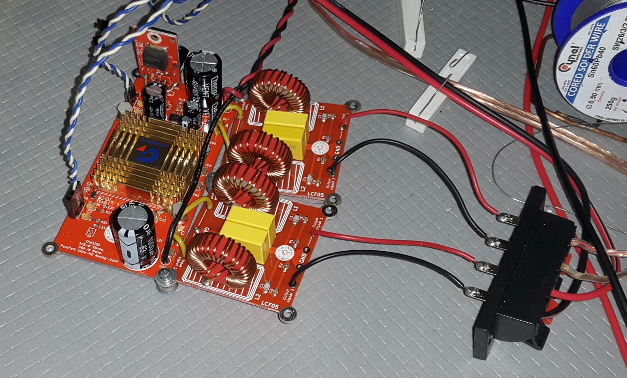
I've just received the Russian TPA3255 bundle:
- amp: RDC2-0034a, Усилитель мощности класса D. TPA3255, PurePath, 315Вт Stereo или 600Вт Mono | купить в розницу и оптом
- output filters: LCF05, Выходной LC-фильтр второго порядка для усилителей мощности класса D | купить в розницу и оптом
- DC/DC convertor: RDC1-0013 15V, DC-DC преобразователь 60В / 15В, 1.3А, LM2575HV | купить в розницу и оптом
Forgot to buy the cooler: VC-D(S), Кулер для видеокарты , подшипник скольжения | купить в розницу и оптом
But I found one on an old PC mainboard Gigabyte
For PSu I use transformer and 10000uF cap and about 40V after the cap.
For now the P3A of Rod Elliot sounds better on the same PSU(+/-40V)...
I've bought the bundle to use it as evaluation board to test different output inductors and capacitors.
This bundle is around 50 euro with the shipping to Moscow, after that a friend of mine brought it to Bulgaria.
You should be able to use the ADR line as a Chip Select :
On your UC connect a gpio out port to the ADR line of each TAS 3251 then connect together all SDA and SCL line. By software set all ADR line to 0. When the software wants to use a specific TAS3251, it set its ADR line to 1 and use I2c@ 4B, 96 and 97. Never use the @ associated with ADR =0.
Wtih this method you’ll be able to use an UC with a single I2C I/F wich will be probably cheaper and with smaller pin count. And you be able to drive as many TAS you want, for example for a 7.1 system…
You should be able to use the ADR line as a Chip Select :
On your UC connect a gpio out port to the ADR line of each TAS 3251 then connect together all SDA and SCL line. By software set all ADR line to 0. When the software wants to use a specific TAS3251, it set its ADR line to 1 and use I2c@ 4B, 96 and 97. Never use the @ associated with ADR =0.
Wtih this method you’ll be able to use an UC with a single I2C I/F wich will be probably cheaper and with smaller pin count. And you be able to drive as many TAS you want, for example for a 7.1 system…
Thanks for the tip. Well noted. It looks like an elegant way to deal with the issue.
JMF
Here is the firmware for the microcontroller STM32F042 which includes two TASS3251 at once. Github chipdipru
So based on the above functional spec and advices, the board could have below connectors and Jumpers:
Basic conf:
Additions to be populated if needed:
Any advice on standard, proven, (possibly cheap) connectors for the I2S and I2C connections ?
Is it possible to find Ribbon cable / coonectors trhat allow hobbyist to easily make connection cables between boards ? I would be happy to avoid having a mess breadboard type connections.
JMF
Basic conf:
- Connector: I2S (MCLK, SCLK, LRCK, SDIN, ???SDOUT)
- Connector: (I2C SDA, SCL, GND, ??3.3V)
- Pin Header: ADR, RESET_AMP, DAC_MUTE, FAULT, CLIP, GND
- Pin Header Fred Adjust
- Pin Header: Volume (+3.3V, AI, GND)
- Pin Header: ON/OFF (DI, GND)
- Pin Header for uC programming
- Jumper for ADR
- Jumper for RESET_AMP / Reset controlled by uC
Additions to be populated if needed:
- Connector: Oscillator Sync Interface (OSC-IOP, GND, OSC-IOM)
- Pin Header: additional I2S
- Pin Header: additional GPIO (GPIO1, ... GPIO5, GND)
- Pin Header: Aux Power 12V
- Pin Header: Auw Power 3.3V
- Connector "grouped I2S-I2C" for chaining boards (MCLK, SCLK, LRCK, SDIN, ???SDOUT, I2C SDA, SCL, GND, ??3.3V)
Any advice on standard, proven, (possibly cheap) connectors for the I2S and I2C connections ?
Is it possible to find Ribbon cable / coonectors trhat allow hobbyist to easily make connection cables between boards ? I would be happy to avoid having a mess breadboard type connections.
JMF
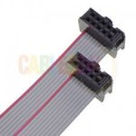
You can use connectors for flat cable with 2.54mm pitch. It is easy to crimp them with a vice. 1.27 should be doable too.
https://fr.farnell.com/w/c/connecte...-s-&range=inc-in-stock|exc-delivery-surcharge
https://fr.farnell.com/w/c/connecte...-s-&range=inc-in-stock|exc-delivery-surcharge
You know, I don't do it for the money. If it had to pay just for my time, then it would cost much more than the limit you propose. There are very good alternatives like the hypex nCore or the 3e-audio offer. So it does not makes sense for to try to build a commercial product, with procurement, soldering, after sale.
However, it could be of interest for a Maker, with niche needs that would fit, interested with experimenting with the chip, but not with the TI EVM board
For me, the learning is the reward (and it is still not the end of the road).
JMF
You could solder SMD components yourself. You need stencil (6 usd at jlpcb) and small oven that you can buy for 200-300 usd plus some thigns that you already have like magnifier, soldering iron etc.... I do it regularly for development purposes. It enables you to iterate quickly. You can also do small series.
for that you need to consider few things:
1) Keep passive components 0603 size or 0805 for bigger capacitor (i.e. 22u). 0603 you can hand solder if needed, anything less then 0603 it is difficult/impossible to manage. Also, it is easier to keep stock of passive components one size. 0603 you can hand solder/change if needed i.e. to tweak and quickly test.
2) Design one side only for SMD components. For TH components you can do as you like.
3) try to avoid small components i.e. for power supply, always look for alternative, it may be for example that one same component has several housings solutions. For diy SMD mounting, the bigger the better. you can do small ones as well, but not worth trouble if there is an alternative. Also, stencil needs to be clean for possible future use, small openings are more difficult to clean. You loose more time on cleaning usually then on actual soldering.
As for the price of the end solution without even looking BOM and what are you doing I am pretty sure you are not optimized. Passive components resistors, capacitors as said before keep 0603 size and forget, they are dirty cheap. Focus on all other components and check price in China. If component is not massively available in China try to find alternative, usually there is popular alternative that cost fraction of the price and is easy to get. If you correctly do this process you will be able to assemble PCBs i.e 20 pcs that cost same if you would assemble thousands in Europe, so you can be price competitive - this is how Chinese ppl do it (they are great entrepreneurs).
Regards,
Hrvoje
Hi,
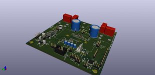
After some thinking and homework, here is the schemqtics of the TAS3251 with an on board micro-controller to allow for an versatile amplifier with I2S input.
The chosen uC is a stm32F030C8T6 chip (0.83$ and JLCPCB basic part).
The uC will be able to perform Master or Slave roles. In master role:
- board Power ON sequence: /RESET_AMP after sufficient delay after power reached a sufficient level,
- board Voltage monitoring: /RESET_AMP in case of insufficient voltage (about 20V for ex),
- board FAULT management: /RESET_AMP after FAULT
- Power OFF sequence: /MUTE and /RESET from a GPIO state,
- DSP registers programming of local board and slave boards,
- Volume management via board pot and update of volume registers with I2C for local board and slave boards,
- Software Mute function (via I2C).
Basic conf:
- Connector: I2S (MCLK, SCLK, LRCK, SDIN, SDOUT)
- Connector: I2C (SDA, SCL, GND, 3.3V - Grove pinout)
- Pin Header: ADR, RESET_AMP, DAC_MUTE, FAULT, CLIP, GND
- Pin Header Fred Adjust
- Pin Header: Volume by external pot (+3.3V, AI, GND)
- Pin Header: 9xGPIO (9xDI, GND) for various purposes
- Pin Header for uC programming (same as pinout as ST-Link)
- Jumper for ADR
- Jumper for RESET_AMP / Reset controlled by uC
- Connector: Oscillator Sync Interface (OSC-IOP, GND, OSC-IOM)
- Pin Header: additional I2C
- Pin Header: Aux Power 3.3V, 12V, 15V
Attachments
Last edited:
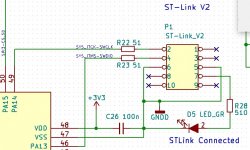
STLink
Great !
An alternative (or complement) to using a SWD pinout for the STLink could be to use the pinout of the cheap STLink V2 adapter (2$ on Aliexpress or Ebay) and to use a 2*5 pin 2.54 header on your pcb. This will allow you to connect your board through a firm and reliable flat cable which provide much better connection than ‘flying’ wires between the board and your STLink adapter. This may be particulary relevant in a class D power amplifier environment.
And this may also help DIYer playing with your amp without being equipped with a Nucleo or Discovery board to use as a STLink.
The new STLINK V3MINI ( STLINK-V3MINI - STLINK-V3 compact in-circuit debugger and programmer for STM32 - STMicroelectronics ) is very interesting too. Cable and connector are 1.27 pitch.
What will be the price for two boards ?, those are potentially perfect companions of those ones : Up2Stream WiFi Audio Receiver Module,circuit Board DLNA AIRPLAY output in order to build two ways active xover connected speaker.
Chris
Attachments
Hello,
About the price of boards, I had prtoposed the below thing. Still no intention to propose fully assembled boards.
Remaining components would be the TAS3251, Wurth 7443631000 coils, Elna SILMIC II, EGPD500ELL242MM30H, B32652A3684J, Wuerth_74404064151, Heatsink, terminal blocks, pinhead headers, and few 0805 and 1206.
Can do the deytailed remaining BOM if some are interested.
JMF
About the price of boards, I had prtoposed the below thing. Still no intention to propose fully assembled boards.
To look if there would be some interest.
My intention is to have a set of 10 boards manufactured at JLCPCB with as many as possible components fitted. This would exclude "expensive components" like the TAS3251, coils, all through holes, connectors, headers... and some of the SMD.
I think that I would have 5-6 boards left. Would there be some interest if I was selling them about:
- Real cost rounded to the next 5€ (should be about 10 or 15€) + shipping to the person if booked now,
- Double manufacturing price + shipping to the person once tested and demonstrated as working.
This would be a board where about 70% of the components where already there, with some remaining SMD and Through Hole to be procured and soldered.
If interested, please let me know.
JMF
Remaining components would be the TAS3251, Wurth 7443631000 coils, Elna SILMIC II, EGPD500ELL242MM30H, B32652A3684J, Wuerth_74404064151, Heatsink, terminal blocks, pinhead headers, and few 0805 and 1206.
Can do the deytailed remaining BOM if some are interested.
JMF
Last edited:
Great !
An alternative (or complement) to using a SWD pinout for the STLink could be to use the pinout of the cheap STLink V2 adapter (2$ on Aliexpress or Ebay) and to use a 2*5 pin 2.54 header on your pcb. This will allow you to connect your board through a firm and reliable flat cable which provide much better connection than ‘flying’ wires between the board and your STLink adapter. This may be particulary relevant in a class D power amplifier environment.
And this may also help DIYer playing with your amp without being equipped with a Nucleo or Discovery board to use as a STLink.
The new STLINK V3MINI ( STLINK-V3MINI - STLINK-V3 compact in-circuit debugger and programmer for STM32 - STMicroelectronics ) is very interesting too. Cable and connector are 1.27 pitch.
What will be the price for two boards ?, those are potentially perfect companions of those ones : Up2Stream WiFi Audio Receiver Module,circuit Board DLNA AIRPLAY output in order to build two ways active xover connected speaker.
Chris
OK will update for the STLink V2 adapter.
JMF
Another late suggestion...
Currently, the DSP coefficients are stored within the flash of the uC. Changing the coeff, will require to flash the uC, either by recompiling the code then uploading it, or by flashing only a dedicated part of the flash (with STMCubeProgrammer) containing the array with the coefficient. This second method will be much simpler than the first.
Having an onboard eeprom and let the uC manage it could be an alternative. For example, running on the board a basic serial monitor (attached to serial or I2C) will allow to update the TAS registers live and to save them in eeprom in order to retrieve them at next power up or reset.
If the TAS3251 has close to 100 registers a 24C64 eeprom will handle many. Eeprom may also contains other parameter such as the number of TAS to manage or filter presets, etc…resulting in a stand-alone device.
A 24C64 is 0,11$ (!) at JLCPCB.
Chris
- Home
- Amplifiers
- Class D
- [design log] Neat 2x170W I2S in, I2C controlled, integrated DSP amp (TAS3251)