Another late suggestion...
Currently, the DSP coefficients are stored within the flash of the uC. Changing the coeff, will require to flash the uC, either by recompiling the code then uploading it, or by flashing only a dedicated part of the flash (with STMCubeProgrammer) containing the array with the coefficient. This second method will be much simpler than the first.
Having an onboard eeprom and let the uC manage it could be an alternative. For example, running on the board a basic serial monitor (attached to serial or I2C) will allow to update the TAS registers live and to save them in eeprom in order to retrieve them at next power up or reset.
If the TAS3251 has close to 100 registers a 24C64 eeprom will handle many. Eeprom may also contains other parameter such as the number of TAS to manage or filter presets, etc…resulting in a stand-alone device.
A 24C64 is 0,11$ (!) at JLCPCB.
Chris
This is a very good idea!
I have implemented this structure in another amplifier and it works great.
If you flash a bootloader you can also update the flash via the same serial interface.
And besides I2C commands you can allow all kinds of other commands via this interface (volume control, LEDs, reading GPIO etc).
Every biquad needs 20 bytes, so you can do the math on how many KB you need. Also depends on if you store the values as strings (ASCII) or as byte values.
OK, so the 10 foreseen boards look allocated:
- 1xDoctormord,
- 2xAIM65
- 2xXRK91
- 2xCapt Grogg
- 3 JMF
However, be a bit patient, as this is a side activity and I'm a slow guy.
JMF
- 1xDoctormord,
- 2xAIM65
- 2xXRK91
- 2xCapt Grogg
- 3 JMF
However, be a bit patient, as this is a side activity and I'm a slow guy.
JMF
About the EEPROM, let's give it a try as several find it a good idea. But I'm still puzzled about the use case. Could you detail how you see it ?
The uC will have 2xI2C exposed:
- I2C1 is the one connected to the TAS3251. It is also connected to J13. In Master mode, the uC is expected to be the master of the bus. It is the "main" I2C of the board
- I2C2 is connected to straight to J19. Could be used to control another board...
I understand that the uC would (could) read from the EEPROM the coefficients (among other things).
In your idea, how data would be written in the EEPROM ?
On I2C1 or I2C2 ?
How would be allocates the Master/Slave roles between the "writer"and the board uC (EEPROM and TAS3251 being Slaves)?
Should I put solderbridges or jumpers for E0-E1-E2 (Eeprom I2C address) ?
I propose to keep /WC floating to allow writing to the Eeprom
By the way, crosschecking of the board would be helpful to gain time and avoid losing money. I can share the KiCAD files by PM.
JMF
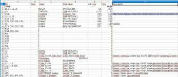
This morning, I looked at the list and cost of "remaining components" to add to the JLCPCB Assembly. See attachment below. I arrive to about 60€ for one board with ordering to Digikey (without shipping costs, remaining small SMDs, pinhead headers).
As expected, the cost derives mainly from, by importance rank:
- output coils (26€),
- TAS3251 (12€),
- Heatsink (6.3€),
- Speakers and power supply connectors (5.3€)
Ordering a batch of coils directly to Wurth helps as the price drops to around 3€ per coil for 40 ordered.
As expected, the cost derives mainly from, by importance rank:
- output coils (26€),
- TAS3251 (12€),
- Heatsink (6.3€),
- Speakers and power supply connectors (5.3€)
Ordering a batch of coils directly to Wurth helps as the price drops to around 3€ per coil for 40 ordered.
Attachments
Interesting project especially as I'm looking to do a Linkwitz LXmini project some time.
In that context, would it be possible to provide two of these boards from a single I2S source, say an Amanero or JLSounds board, and then derive the required equalised LXmini outputs (Left Hi/Lo & Right Hi/Lo) but with overall volume control from a single potentiometer?
Thanks
In that context, would it be possible to provide two of these boards from a single I2S source, say an Amanero or JLSounds board, and then derive the required equalised LXmini outputs (Left Hi/Lo & Right Hi/Lo) but with overall volume control from a single potentiometer?
Thanks
AIM65,
Would this pinout be correct (attached below)? I respected the pin numbers you proposed, but there is a risk that the odd/even numbering is not the same for the footprint. So I prefer to check.
Additional question: do you confirm that there is no need of conection to NRST ?
JMF
Would this pinout be correct (attached below)? I respected the pin numbers you proposed, but there is a risk that the odd/even numbering is not the same for the footprint. So I prefer to check.
Additional question: do you confirm that there is no need of conection to NRST ?
JMF
Great !
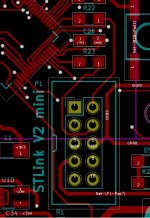
An alternative (or complement) to using a SWD pinout for the STLink could be to use the pinout of the cheap STLink V2 adapter (2$ on Aliexpress or Ebay) and to use a 2*5 pin 2.54 header on your pcb. This will allow you to connect your board through a firm and reliable flat cable which provide much better connection than ‘flying’ wires between the board and your STLink adapter. This may be particulary relevant in a class D power amplifier environment.
And this may also help DIYer playing with your amp without being equipped with a Nucleo or Discovery board to use as a STLink.
The new STLINK V3MINI ( STLINK-V3MINI - STLINK-V3 compact in-circuit debugger and programmer for STM32 - STMicroelectronics ) is very interesting too. Cable and connector are 1.27 pitch.
What will be the price for two boards ?, those are potentially perfect companions of those ones : Up2Stream WiFi Audio Receiver Module,circuit Board DLNA AIRPLAY output in order to build two ways active xover connected speaker.
Chris
Attachments

Last edited:
Reply to posts #183 & 185
About use cases and eeprom:
Use case 1: Setup and tuning of the TAS filter (for example during an active xover design). We will have to do a lot of test & trial: be able to load as easily as possible the TAS registers.
This will require more software on the Uc but also a persistent storage of the parameters set by end user tuning: in an eeprom.
This will also require some kind of user interface. As input device you currently have a potentiometer, I think a rotary encoder will be better, with at least two pushbuttons. As output device it depends on your application: from some Leds to a basic I2C screen such a LCD1602
About I2C
Eeprom could be connected to I2C1 with the TAS and the other TAS board. Eeprom, TAS, even LCD1602 will be slave, the Uc will be master and other master (multimaster compatible only) could be connected for use case 1. “Writer” of the Eeprom will be Uc, if this was your question
About STLink
Yes pinout is ok. Picture is a layout of a working prototype. Take care of the footprint of the connector, do not install parts too close to it. Your footprint is for header only, mine is for a complete pcb connector which is larger ( https://fr.farnell.com/molex/70246-1004/connect-header-10-voies-2-rangs/dp/1392408 ).
There’s no NRST connection, I think SWD issue a soft reset, which is ok. But it’ll be very useful to have on your board a smd reset button and also a debugging and diagnostics Led on a GPIO.
About your design goal
I haven’t followed the whole thread, so I’m not clear about master and slave boards. Slave boards could be boards without Uc, entirely managed by the Uc of the master board or the external bus master (if multimaster…). Is it the plan ?
Chris
About use cases and eeprom:
Use case 1: Setup and tuning of the TAS filter (for example during an active xover design). We will have to do a lot of test & trial: be able to load as easily as possible the TAS registers.
Question is, how to change the TAS setup after initialization?
- We can change the registers values in the Uc source code, recompile and flash in the UC…it's going to get tiresome fast.
- We can try to flash the Uc with the sole table containing the values of the TAS registers.
- We also can use live method but it’ll will require another system able to manage the TAS through I2C as a multimaster host. At the end of the setup the register values will be copied in the source code, then recompiled and uploaded in the Uc, wich at next startup will setup the TAS with the right values. If your external host is not multimaster (ie Rpi as said in post#142) solution will be to bounce on the Uc : Rpi as master will talk to Uc I2C2 as slave which as a gateway will forward to I2C1 as master to the various slave. You’re right, eeprom has very few value for this use case
This will require more software on the Uc but also a persistent storage of the parameters set by end user tuning: in an eeprom.
This will also require some kind of user interface. As input device you currently have a potentiometer, I think a rotary encoder will be better, with at least two pushbuttons. As output device it depends on your application: from some Leds to a basic I2C screen such a LCD1602
About I2C
Eeprom could be connected to I2C1 with the TAS and the other TAS board. Eeprom, TAS, even LCD1602 will be slave, the Uc will be master and other master (multimaster compatible only) could be connected for use case 1. “Writer” of the Eeprom will be Uc, if this was your question
About STLink
Yes pinout is ok. Picture is a layout of a working prototype. Take care of the footprint of the connector, do not install parts too close to it. Your footprint is for header only, mine is for a complete pcb connector which is larger ( https://fr.farnell.com/molex/70246-1004/connect-header-10-voies-2-rangs/dp/1392408 ).
There’s no NRST connection, I think SWD issue a soft reset, which is ok. But it’ll be very useful to have on your board a smd reset button and also a debugging and diagnostics Led on a GPIO.
About your design goal
I haven’t followed the whole thread, so I’m not clear about master and slave boards. Slave boards could be boards without Uc, entirely managed by the Uc of the master board or the external bus master (if multimaster…). Is it the plan ?
Chris
Attachments
This morning, I looked at the list and cost of "remaining components" to add to the JLCPCB Assembly. See attachment below. I arrive to about 60€ for one board with ordering to Digikey (without shipping costs, remaining small SMDs, pinhead headers).
I would also suggest ordering all the small parts together, it is not much difference to you. But a big difference for everyone that has to order a couple SMD's and some headers, and all of them has to pay for shipping.
... So I just missed the option to get 2 boards for myself? Not a humongous loss, more than enough stuff here. But it would be fun to try this TAS3251 solution.
Thanks for the long reply, my understanding or replies below:
I understand that the Eeeprom main benefit will be to have persistent storage of applicative values (use case 1 to be managed either by an external multimaster directly through the TAS, or through the board uC: external system => I2C2 => Board uC => TAS).
In my design, I expose I2C2, 1x Analog, 9xGPIO : so enough to connect rotary encoder, I2C screen, some leds and control buttons. Looks good to me.
OK, Eeprom on I2C1
I have put a jumper for reset of the uC. JLCPCB does not proposes buttons as basic parts, and I already have reached the 10 extended parts limit.
I will try to use a different footprint for the connector, to allow your standard Molex connector to be used.
The intention is to always populate the uC but have different firmwares:
On a slave board, the board uC manages:
- board Power ON sequence: /RESET_AMP after sufficient delay after power reached a sufficient level,
- board Voltage monitoring: /RESET_AMP in case of insufficient voltage (about 20V for ex),
- board FAULT management: /RESET_AMP after FAULT
- Power OFF sequence: /MUTE and /RESET from a GPIO state,
- To Be Confirmed: Jumper for RESET
On a Master board, the board uC manages:
- Slave functions for the local board
- DSP registers programming of local board and slave boards,
- Volume management via board pot and update of volume registers with I2C for local board and slave boards,
- Software Mute function (via I2C).
Reply to posts #183 & 185
About use cases and eeprom:
Use case 1: Setup and tuning of the TAS filter (for example during an active xover design). We will have to do a lot of test & trial: be able to load as easily as possible the TAS registers.Question is, how to change the TAS setup after initialization?
Use case 2: Run a standalone TAS board which could be tuned by end user live: i.e. bass/mid/ treble/tuning, or choose between DSP setup1/setup2/…, or choose filters characteristics for a xover (Low Pass, High Pass, Q, F0, order, etc..), etc…
- We can change the registers values in the Uc source code, recompile and flash in the UC…it's going to get tiresome fast.
- We can try to flash the Uc with the sole table containing the values of the TAS registers.
- We also can use live method but it’ll will require another system able to manage the TAS through I2C as a multimaster host. At the end of the setup the register values will be copied in the source code, then recompiled and uploaded in the Uc, wich at next startup will setup the TAS with the right values. If your external host is not multimaster (ie Rpi as said in post#142) solution will be to bounce on the Uc : Rpi as master will talk to Uc I2C2 as slave which as a gateway will forward to I2C1 as master to the various slave. You’re right, eeprom has very few value for this use case
This will require more software on the Uc but also a persistent storage of the parameters set by end user tuning: in an eeprom.
This will also require some kind of user interface. As input device you currently have a potentiometer, I think a rotary encoder will be better, with at least two pushbuttons. As output device it depends on your application: from some Leds to a basic I2C screen such a LCD1602
I understand that the Eeeprom main benefit will be to have persistent storage of applicative values (use case 1 to be managed either by an external multimaster directly through the TAS, or through the board uC: external system => I2C2 => Board uC => TAS).
In my design, I expose I2C2, 1x Analog, 9xGPIO : so enough to connect rotary encoder, I2C screen, some leds and control buttons. Looks good to me.
About I2C
Eeprom could be connected to I2C1 with the TAS and the other TAS board. Eeprom, TAS, even LCD1602 will be slave, the Uc will be master and other master (multimaster compatible only) could be connected for use case 1. “Writer” of the Eeprom will be Uc, if this was your question
OK, Eeprom on I2C1
About STLink
Yes pinout is ok. Picture is a layout of a working prototype. Take care of the footprint of the connector, do not install parts too close to it. Your footprint is for header only, mine is for a complete pcb connector which is larger ( https://fr.farnell.com/molex/70246-1004/connect-header-10-voies-2-rangs/dp/1392408 ).
There’s no NRST connection, I think SWD issue a soft reset, which is ok. But it’ll be very useful to have on your board a smd reset button and also a debugging and diagnostics Led on a GPIO.
I have put a jumper for reset of the uC. JLCPCB does not proposes buttons as basic parts, and I already have reached the 10 extended parts limit.
I will try to use a different footprint for the connector, to allow your standard Molex connector to be used.
About your design goal
I haven’t followed the whole thread, so I’m not clear about master and slave boards. Slave boards could be boards without Uc, entirely managed by the Uc of the master board or the external bus master (if multimaster…). Is it the plan ?
Chris
The intention is to always populate the uC but have different firmwares:
On a slave board, the board uC manages:
- board Power ON sequence: /RESET_AMP after sufficient delay after power reached a sufficient level,
- board Voltage monitoring: /RESET_AMP in case of insufficient voltage (about 20V for ex),
- board FAULT management: /RESET_AMP after FAULT
- Power OFF sequence: /MUTE and /RESET from a GPIO state,
- To Be Confirmed: Jumper for RESET
On a Master board, the board uC manages:
- Slave functions for the local board
- DSP registers programming of local board and slave boards,
- Volume management via board pot and update of volume registers with I2C for local board and slave boards,
- Software Mute function (via I2C).
I would also suggest ordering all the small parts together, it is not much difference to you. But a big difference for everyone that has to order a couple SMD's and some headers, and all of them has to pay for shipping.
... So I just missed the option to get 2 boards for myself? Not a humongous loss, more than enough stuff here. But it would be fun to try this TAS3251 solution.
Update:
OK, so the 10 foreseen boards look allocated:
- 1xDoctormord,
- 2xAIM65
- 2xXRK91
- 2xCapt Grogg
- 3 JMF
- Waiting list 2x KaffiMann
I have to investigate the assembly options on JLCPCB to have slightly more quantities.
My main concern is that I won't be sure all this works before building the first prototype. And I just want to share this with people that assume the risk (and confidence in handsoldering a HSSOP 56 pin).
About what you propose for small SMD parts, I understand your idea. Could be done for small quantities, but will lenghen delays, because you will have to wait my orders 🙂. And as at the end I won't propose kits, ordering will be needed.
JMF
Hello JMF11,
I’ve made today a quick review of TAS3251 Evaluation Module documentation and also the Process flow document, this is pretty impressive! But I have a major concern regarding my future ability to produce a configuration file:
TI software PurePath Console seems to require a TI EVM board in order to gain access to a TAS3251 and configure it.
Purepath run on a PC, access to the EVM board Uc (MSP430) through USB and bounce on it to access the TAS through I2C. Without an EVM board we won’t be able to access the TAS with Purepath.
Does someone know if there’s a way to use Purepath on a TAS without an EVM board?
If not, can Purepath be used disconnected in order to produce configuration file, we’ll have to upload on the TAS (Use case 1) ?
You mention this in post#9 but I haven’t seen the answer
How work the power supervisor ?. It’s a copy of the one on EVM board but on EVM it use a dedicated chip: TPS3802. In addition on steady state, you’ll have 12*3.3/(3.3+8.2) = 3.4V on PA1 which is > Uc supply… Alternatively you can use internal DAC of Uc to measure voltage on two gpio port. On each port use 3.9k to ground and 47k to +12 for one and to VDD for the other one. On each port also add a 100n cap to GND and a dual reverse biased Schottky diode connected to GND and to 3.3V (ex: BAS40-04,215 @JLCPCB). With the DAC, you’ll be able to monitor those two supplies by software then to manage TAS reset.
Chris
I’ve made today a quick review of TAS3251 Evaluation Module documentation and also the Process flow document, this is pretty impressive! But I have a major concern regarding my future ability to produce a configuration file:
TI software PurePath Console seems to require a TI EVM board in order to gain access to a TAS3251 and configure it.
Purepath run on a PC, access to the EVM board Uc (MSP430) through USB and bounce on it to access the TAS through I2C. Without an EVM board we won’t be able to access the TAS with Purepath.
Does someone know if there’s a way to use Purepath on a TAS without an EVM board?
If not, can Purepath be used disconnected in order to produce configuration file, we’ll have to upload on the TAS (Use case 1) ?
You mention this in post#9 but I haven’t seen the answer
I also have a concern about the size of the eeprom, configuration of the TAS seems complex : there’re pages, books, etc... It is preferable to calculate the real TAS cumulated register size in byte and multiply by lets say 4 to determine the min size of the eeprom. A 24C64 may not be sufficient.I just get the access to the TAS3251 module in TI configuration tool PPC3. Good to have. I will now study it and confirm the possibility to configure the chip without having the TAS3251EVM board.
JMF
How work the power supervisor ?. It’s a copy of the one on EVM board but on EVM it use a dedicated chip: TPS3802. In addition on steady state, you’ll have 12*3.3/(3.3+8.2) = 3.4V on PA1 which is > Uc supply… Alternatively you can use internal DAC of Uc to measure voltage on two gpio port. On each port use 3.9k to ground and 47k to +12 for one and to VDD for the other one. On each port also add a 100n cap to GND and a dual reverse biased Schottky diode connected to GND and to 3.3V (ex: BAS40-04,215 @JLCPCB). With the DAC, you’ll be able to monitor those two supplies by software then to manage TAS reset.
Chris
I do not know a way to use the chip directly with PPC without the EVM, but for the final application you would still want an eeprom/flash construction because of the volatile memory.
PPC allows register dumps without an EVM connected. Standard procedure would be to export a header (.h) file, include it in a microcontroller program and boot up via the bootup procedure described in the datasheet.
A 24C64 might not be sufficient indeed. Mainly depends on how you store the DSP data. A 256kb eeprom costs 10 cents more, so I would go for that.
Hi,
About the usage of PPC, same answer as Lutkeveld => it generates the header file with all values (and code to load it). Not as good as having the EVM board but looks acceptable to me.
What I liked when I started the project was the idea that the TAS3251 was "the best of TI engineering for a I2S input powerfull amp, with minimum components, still possible to handsolder".
However, I like less the fact that you have to request TI access to PPC and TAS3251 associated module and all is designed to rely on TA boards. The Analog Device tools seem more "open".
If I was to do lot of filter trials and so on, I would explore using the board as a "straight" amp, feeded with a Nucleo running Audioweaver (free for hobbyist on stm32). This is super tunable live. When converged, I would stay like that or mimic config in PPC and dump on the board uC the resulting coeff.
For the Eeprom size, I had made the calculations about needed size for one set of coeff to check that the selected uC was OK. Hope I have written the result somewhere. Have to check.
As of today, the voltage monitoring to implement the supervisor function is connected to one uC Analog Input. Interested to discuss that part of the circuit.
Have to go now,
JMF
Zoudio
Hi Lutkevled,
Your "ZOUDIO AIO4CH" seen in another threat is a very nice product !. Did you use PurePath Console connected to the TAS5825 via an EVM or disconnected via header files to design your host software ?
If not secret, which USB adapter did you use for I2S and I2C ? I see no candidate chip on the board pictures, maybe on the other side of the pcb ? 🙂
I do not know a way to use the chip directly with PPC without the EVM, but for the final application you would still want an eeprom/flash construction because of the volatile memory.
PPC allows register dumps without an EVM connected. Standard procedure would be to export a header (.h) file, include it in a microcontroller program and boot up via the bootup procedure described in the datasheet.
A 24C64 might not be sufficient indeed. Mainly depends on how you store the DSP data. A 256kb eeprom costs 10 cents more, so I would go for that.
Hi Lutkevled,
Your "ZOUDIO AIO4CH" seen in another threat is a very nice product !. Did you use PurePath Console connected to the TAS5825 via an EVM or disconnected via header files to design your host software ?
If not secret, which USB adapter did you use for I2S and I2C ? I see no candidate chip on the board pictures, maybe on the other side of the pcb ? 🙂
ZOUDIO AIO4CH – Z O U D I O
Got it : there's a small usb to serial adapter which could be plugged in the main board on the programmer connector (J1 ?).
Presumably U3 is an Uc. Is U7 a serial eeprom ?
Got it : there's a small usb to serial adapter which could be plugged in the main board on the programmer connector (J1 ?).
Presumably U3 is an Uc. Is U7 a serial eeprom ?
That's correct.
The board runs a 1.1 flow (seperate biquads possible for each channel) and the tool knows the register map. When you press upload it pulls all settings together, calculates the coefficients, and sends a command over the serial port.
The I2C commands are structured like this:
I2C <AMP1/AMP2/DUAL> <BOOK> <PAGE> <REGISTER> <VALUE0> … <VALUE19>
For up to 20 values (biquad has 5 coefficients, 4 bytes each)
The board has a serial parser that decomposes the command and runs it immediately, but the strings that are send by the tool are also saved on the EEPROM to be retrieved every time the board starts up.
This sames structure can be applied to the TAS3251, which I am actually looking at for a higher power version of the AIO4CH. The tool can request model type via serial, so if it has the register map of the TAS3251 it can use the same tool. The firmware of the uC can also be updated via the same serial port.
Maybe due to size / cost constraints it would be better to make it 2-channel by default and make it expandable by stacking/daisychaining. Also more input options would be nice (spdif, usb, I2S). Expanding the input source selection and laying out the TAS3251 including partselection would take the most time. Could maybe be a nice community effort.
Thanks.
I fully agree :
I fully agree :
- using serial rather than I2C to attach an external host will be easier : we’ll be able to use low cost usb to serial adapter (but yours is neat) and eventually to be able to use your control software…
- Daisy chaining the board via serial will also simplify interconnexion and master/slave boards management and board software development
- adding an AK4113 and a 74AC257 will easily provide spdif and toslink access for the TAS with very few additionnal code, USB will be complex/expensive
I personnally does not like so much the Spdif and toslink interfaces, in a KISS approach. Stm32 with USB connectivity and SAI has hudge abilities for what we are doing. The SAI can even have its own Audio clock for perfect timing. I2S provides the clock. All this has the potential to reduce Jitter.
And for most of us, music are files now. So having a full digital chain makes lot of sense... But for sure Spdif / Toslink will appeal to some.
And for most of us, music are files now. So having a full digital chain makes lot of sense... But for sure Spdif / Toslink will appeal to some.
I struggle to find the needed sizing of the registers in the datasheets. I did a dump for 1.1 processflow from PPC, ans I arrive to someting like 2100 lines of 2 bytes => 4200k ?
64k Eeprom would allow to store about 15 flows...
But maybe I misinterpret the thing ?
@lutkeveld: would you have other orders of magnitude in mind (especially from the TAS5825)?
JMF
64k Eeprom would allow to store about 15 flows...
But maybe I misinterpret the thing ?
@lutkeveld: would you have other orders of magnitude in mind (especially from the TAS5825)?
JMF
Last edited:
AIM65: the interface you would use for daisy chaining would be the I2C control interface to the TAS3251. That way you have one master uC, which can scan the I2C bus for all connected TAS devices.
JMF11: The register dump takes about 10kB when compiled and stored in flash. But with my EEPROM structure where you save the byte values in a space-seperated string you can store only 23 actual byte values in a complete string (128 bytes). Also, the register dump contains a lot of registers that are not directly filters. They are probably internal registers that determine the dataflow and processing characterics.
So what I do is I store the register dump in flash with all filters set to default/allpass and then when it boots up it first writes the default, and then overwrites part of it with the registers from the EEPROM. I have a 256kb EEPROM on board, just to be sure, but currently when all filters are set (excluding DRC, have not implemented that in my tool yet), it takes about 30kB.
Can you explain how the SAI on the STM32 would work? It would provide I2S I reckon, but what is the source?
- Home
- Amplifiers
- Class D
- [design log] Neat 2x170W I2S in, I2C controlled, integrated DSP amp (TAS3251)