Yes, I will do that, but I will need to wait for my next days off, 7 days from now.can you reestablish the 7812 just temporarily to see that there is no damage on the TPA3255 chip?
Another thought; the TPS7A4700 regulator board has an ENABLE pin.
Maybe I can trigger this ENABLE pin when the main power supply is up ...
I'm sure there are many ways to do this, but it seems to me a simple way would be to initiate this from the amp's 7812 regulator - connect this to a 12V relay, then the switch output of the relay to the TPS7A4700 ENABLE pin??
Update: I temporarily reversed this modification, and the amp still works fine.
I also did a test where I connected a switch to the ENABLE pins of the TPS7A4700 regulator, then I turned on the main power to the amplifier, then switched on the 12V supply slightly later. No matter what delay I used, I always just got the electronic beating noise from the speakers.
So I can just give up and reverse the modification, but I have gone to a certain amount of effort to install the TPS7A4700 12V regulator ...
does anyone have any idea why feeding an external 12V into the board is not working?
There should be no problem with power/heat, my regulator has a substantial heatsink -
Single Rail TPS7A4700 Ultra Low Noise</br>Power Supply
... but I have made a little progress - I Googled "TPS7A4700 output capacitor" and I see other implementations of the TPS7A4700 are using significantly larger caps at the output than the 0.1uF that my reg board has.
Just now I put an additional 680uF Panasonic FM cap across the reg's output, and now I can hear music ... along with a lot of hum! But at least the beating noise is gone.
Then I added a second 680uF cap, and the hum is still bad, but less than before.
So maybe it's just a question of cap value at the output? Maybe next try a lower value, like 200uF or so?
Anyway, out of time for now, must leave for work.
Last edited:
Welcome back from work.
The datasheet shows that the TPS7A4700 is a collector output design, as most low-drop regulators are. That means you need a good size capacitor at the output if you have significant variations in the load current. For the time being I would leave the 680uF at the output because it is hardly that creating the hum. I see no rectifier at the input of the TPS7A4700 board so you feed it with DC. From what do you feed the board and with which voltage level?
Do you have access to an oscilloscope? A multimeter is generally far too slow to detect DC voltage swings. However, you can use the multimeter AC settings to get an indication of noise on a DC line.
Last edited:
The rectifier is on the underside of the board.I see no rectifier at the input of the TPS7A4700 board
My transformer is 10VAC/0.6A
Item # F4-10, Chassis Mount Quick Pack™ Power Transformers On Triad Magnetics
Oh, I now think my transformer may be under-rated.As I recall it, the TPA3255 draws several hundred mA on the 12V line.
With the 680uF cap in place, I just checked voltages now -
15.3V after the bridge rectifier - good.
11.2V at the output - not quite good enough.
I see three possible reasons for such hum.
1) Higher ripple at the regulator input capacitor (5600uF) than what we expect. If no oscilloscope, try to measure with the DMM in AC setting.
2) Higher ripple at the regulator output capacitor (680uF) than what we expect. If no oscilloscope, try to measure with the DMM in AC setting.
3) You have created a ground-loop. Did you connect the "-" from the output of your regulator board to where the 7812 had its ground-pin connected or did you connect "-" to the general "-" supply for the amplifier board? The thing is that you now have two transformers and two bridge rectifiers that each generate rectification noise at the hum frequency. If rectification noise is introduced in two different places on the ground conductor it may be heard. My intuition tells me that joining "-" from the first bridge rectifier with "-" from the second bridge rectifier and no more should result in minimum rectification noise.
Last edited:
Yes. And the reg board is mounted to the chassis on nylon standoffs.Did you connect the "-" from the output of your regulator board to where the 7812 had its ground-pin connected
Thanks for your help FauxFrench. As you say, I need to check for ripple at the input and output of the reg. This is beyond my ability, but I will talk to some technicians at my company to see if they can help me.
Before that time, though, I might proceed with a 2nd modification that I was planning - to bypass the SE-diff input stage of the amp, and use the balanced outputs of my DAC.
Once this is done, I can disable power to the opamps, and this will affect the current demand upon the 12V supply.
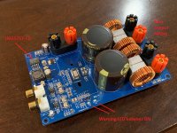
Is it just me or are all these issues observed in the other eBay/AliExpress/Amazon Chinese blue TPA3255’s?
These boards have errors on them that prevent them from being a practical amp. I bought two from different vendors and one was on Amazon. Still same problem because same layout.
1. The error lights for fault and OTW are always on when operating normally. How useful is that?
2. The amp has no remote reset capability, so if your input RCA has a glitch, the amp goes onto protect error mode and shuts down. The only way to reset is to unplug the power input. That is every inconvenient as the errors can happen with something like hot plugging in the RCA to a source.
3. I was unable to get more than 48Vpp out of it with a 51v PSU. I believe the hardwire soldered or layout based setup mode jumpers were incorrect and so it is not working in BTL mode which should give a swing of close to 2x48v minus MOSFET dropout on each end or 96v-8v or +/-78v theoretical max or 27.6Vrms for 190w into 4ohms. 48Vpp into 4ohms is only 72W - a far cry from 200W,
4. It has an LM2575T-12 switching step down regulator for making 12v from the 48v input. The "T" variant of this regulator is only good for 40V max input. It needs the LM2575HV-12 version which can go to 60v input. So I suppose the regulator must be sort of working because it makes music with a 48v to 51v supply, but who knows what the regulator is doing in terms of regulation.
5. The measured harmonic distortion profiles were not close to the specified levels of the TI reference design.
Basically, I can’t believe they went into production of tens of thousands of these boards without anyone catching these glaring errors.
Attachments
Last edited:
Basically, I can’t believe they went into production of tens of thousands of these boards without anyone catching these glaring errors.
Who'd have thought?
I'm not exactly shocked...

I tried twice already on two separate "blue" boards. Maybe both are lemons? I had sufficient drive voltage headroom as preamp was +/-15v rail. If someone else can please test the Aliexpress/eBay/Amazon blue TPA3255 with a clipping test, that might confirm that I have lemons or flawed design. Redjr has one on his shelf... hint hint...
When you have lemons, make lemonade as they say.
When you have lemons, make lemonade as they say.
Last edited:
- Home
- Amplifiers
- Class D
- What is wrong with TPA3255?