I did buid one based on OP's schematic. I'm however having some problems with it.
At +/- 90V, it seems to distort at about 20-30W output power and when probing with a scope before the output filter, it seems I'm loosing modulation for a fraction of a second - while the amp distorts sound.
Can anyone point me on what to check to fix this behaviour?
same like Kartino talk
post clear HD pictures from PCB with schematic
how about output Filter ?
Do you have T157 or Arnold MS157
how many turns ?
Many people in Indonesia Build and it works very stable
look Facebook
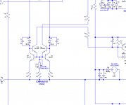
I've attached the schematic i've used, extracted from eagle.
There are some parallel resistors that are actually smd packages placed in parallel to increase dissipation. Also, not all output capacitors (in the output filter) are mounted, - only 3x470nF.
I'm using 3 pairs of IRFB4227 mosfets. Output coil is T157-2 micrometals - 42 turns.
R28 - from my schematic - was changed to a trimmer pot to fine tune dead time setting.
Attachments
I've attached the schematic i've used, extracted from eagle.
There are some parallel resistors that are actually smd packages placed in parallel to increase dissipation. Also, not all output capacitors (in the output filter) are mounted, - only 3x470nF.
I'm using 3 pairs of IRFB4227 mosfets. Output coil is T157-2 micrometals - 42 turns.
R28 - from my schematic - was changed to a trimmer pot to fine tune dead time setting.
you have old schematic
1. look PDF
2. Dead time R1 should be 320R
3. look youtube Video 15 min assembled from scratch with Final test
900W RMS
YouTube
Attachments
I already have a finished module based on that old schematic, i'll try to troubleshoot it further.
Increasing R1 (or R28 on my schematic) allows for more power before distorsions kick in (that weird crackling noise when i loose modulation) but at that level, the mosfets will quickly heat up.
On the new schematic, I see that both sides of the diferential pair are matched, one leading to the feedback path and one leading to ground. Most UcD schematics I've seen use this sort of arangement.
Since that's different on my schematic, I gues I could start from here...
Is the pcb for sharing?you have old schematic
1. look PDF
2. Dead time R1 should be 320R
3. look youtube Video 15 min assembled from scratch with Final test
900W RMS
YouTube
Is the pcb for sharing?
I will buy finished assembled PCBs and later finished my PCB,
it saves time to have working model for compare
I've attached the schematic i've used, extracted from eagle.
There are some parallel resistors that are actually smd packages placed in parallel to increase dissipation. Also, not all output capacitors (in the output filter) are mounted, - only 3x470nF.
I'm using 3 pairs of IRFB4227 mosfets. Output coil is T157-2 micrometals - 42 turns.
R28 - from my schematic - was changed to a trimmer pot to fine tune dead time setting.
Ucd needs bigger LPF cap.
Check on that part.
UcD fullbridge SMD version has been succesfully made by my friend, Wahyu Eko Romadhon. Some video also for UcD halfbridge at his channel.
YouTube
Hi Kartino
thanks have download Video and gerber
1. How can change switching frequency for UCD Halfbride and Fullbridge ?
2. How about standby Idle temperatur with UCD Half and Fullbridge amp ?
I have see commercial Class D amp often they have hot heatsinks in standby
3. ...commercial Class D amp QSC PL380 Halfbridge amp have hot air in idle standby - 500V 2x bulky Mosfet 250khz switching frequency
about 150V DC Rail
4. Is it possibile to use FDA69N25 Mosfets for Xlite ? Qg is 77
Did you try GanFET already ? could this work...400 khz should be possibile
650V GaN (Gallium Nitride) AEC-Q101 FET TP65H035WSQA - Transphorm
TP65H035WSQA
VDS (V) min 650
V(TR)DSS (V) max 800
RDS(on)eff (mΩ) max* 41
QRR (nC) typ 178
QG (nC) typ 24
Attachments
you have old schematic
1. look PDF
2. Dead time R1 should be 320R
3. look youtube Video 15 min assembled from scratch with Final test
900W RMS
YouTube
It can use 320 as minimum. Below that will be high risk of mosfet shoot thru. Higher value will increase dead time, but higher pwm speed and lower clarity as well. Proper dead time maybe need your own adjusting but remember the risk, so it must be done carefully.
Using trimpot can manage adjusting the dead time easily, but I prefer use fix resistor.
Hi Kartino
thanks have download Video and gerber
1. How can change switching frequency for UCD Halfbride and Fullbridge ?
2. How about standby Idle temperatur with UCD Half and Fullbridge amp ?
I have see commercial Class D amp often they have hot heatsinks in standby
3. ...commercial Class D amp QSC PL380 Halfbridge amp have hot air in idle standby - 500V 2x bulky Mosfet 250khz switching frequency
about 150V DC Rail
4. Is it possibile to use FDA69N25 Mosfets for Xlite ? Qg is 77
Did you try GanFET already ? could this work...400 khz should be possibile
650V GaN (Gallium Nitride) AEC-Q101 FET TP65H035WSQA - Transphorm
TP65H035WSQA
VDS (V) min 650
V(TR)DSS (V) max 800
RDS(on)eff (mΩ) max* 41
QRR (nC) typ 178
QG (nC) typ 24
1. Switching speed can be adjusted by rise or lower capacitor feedback (220pF - 680pF), and also adjust dead time resistor. Remember, adjusting speed will need re-adjust DCO and inductor. Lower speed pwm will need more inductor uH.
2. Heat is normally no issue. But as core inductor keep heat so you will need at least small fan to balance the heat dissipation and heat release to air. If too hot then maybe too low inductor uH. So need to keep inductor temperature less than 60C at least WITH small fan.
Heat of heatsink mostly no issue with proper dead time setting. Today it is easy to find good mosfet not like old days for QSC. IRFP4227 is a good example, easy to find. With small fan mostly will keep heatsink temperature less than 35C at indonesian ambient.
3. QSC use very very old mosfet, cannot be compared for today.
FDA69N25 yesit can be suitable. But I prefer use IRFP4227. Very light and powerfull.
I have never used GaN. But with IRFP4227 I can run 350kHz easily with Halfbridge and 300kHz with fullbridge. However, for class D actually not need that high. 270kHz and above almost you cannot hear difference.
But using light mosfet and heavy mosfet at the same PWM speed you can hear the difference because of different raise and fall time of switch. No not the PWM speed actually. I had the same conclusion previously but after some trial, 260kHZ is more than enough to have hi fi sound but must be good in raise and fall time, because the clarity actually at that area.
And you know some manufacturer use bulky mosfet.
Then you can beat them easily in the clarity

same like Kartino talk
post clear HD pictures from PCB with schematic
how about output Filter ?
Do you have T157 or Arnold MS157
how many turns ?
Many people in Indonesia Build and it works very stable
look Facebook
Number of turns must be tuned reflect to switching speed. Most of people only tell that number of turns is only about low pass filter. That is wrong. Proper number of turn = stability. Wrong number of turn = kill your amp very soon. That is the key why indonesian DIYers sucessfully make amp stable.
I make a tutorial, but in bahasa indonesia. But you can find reference of LPF design which is the key of big class D amp stability.
Attachments
bahasa indonesiano no problem, google make it easy to translate
Thank you for Tutorial,...Im also in your Facebook group
Is it allowed to post question in english in your FB Group ?
Of cource
Hello Kartino
"But using light mosfet and heavy mosfet at the same PWM speed you can hear the difference because of different raise and fall time of switch. No not the PWM speed actually ......260kHZ is more than enough to have hi fi sound but
must be good in raise and fall time, because the clarity actually at that area."
Sorry for silly question, but Im not learning electronic in University
but please give me example/ reference information
what values are good or bad raise and fall time of switch for Class D / Mosfet Number
Compare to IRFP 4227.... from your experience, which mosfet lost clarity to hear difference against poor raise and fall time.
Many DIY Designs and also Powersoft using long time IRFP250 in their 3500W x2 amps
Hello Kartino
"But using light mosfet and heavy mosfet at the same PWM speed you can hear the difference because of different raise and fall time of switch. No not the PWM speed actually ......260kHZ is more than enough to have hi fi sound but
must be good in raise and fall time, because the clarity actually at that area."
Sorry for silly question, but Im not learning electronic in University
but please give me example/ reference information
what values are good or bad raise and fall time of switch for Class D / Mosfet Number
Compare to IRFP 4227.... from your experience, which mosfet lost clarity to hear difference against poor raise and fall time.
Many DIY Designs and also Powersoft using long time IRFP250 in their 3500W x2 amps
Light mosfet like IRFP4227 will give you more detail and full bass, more tight compared to old mosfet. A typical good mosfet can have about 25ns delay on and off, compared to old mosfet which can have 50ns - 100ns. This will be very significant at PWM higher than 260kHz.
Most factory using old mosfet because it was the best available. Powersoft use very high rails and very difficult to get proper mosfet actually. So to get higher swithing efficiency of switching, powersoft use low speed, about 200kHz. However, even slow, the sound will be still good compared to other class amp at the same power handling amp, because it is also not easy do design class H or GB with better clarity at that power level. Some manufacturer use 250kHz as standard also.
According to DAC/ADC digital sampling now highest sampling is 96kHz and 24 bit, where in class D we can compare, sampling is PWM and bit is duty cycle variation. A 200kHz speed even twice more than best digital sampling. However, digital sampling has no error if within its bit level.
However, class D has switching error, when fall and rise time has big impact to duty cycle in percentage which ideally zero.
I like this circuit from an educational point of view, its got everything that a novel class d amplifier has but some aspects can be reduced for lower part count and a SMD version should be considered with modern parts.
Other more advance techniques can be applied that exceeds a novel design.
1) Improved control loop. (under all circumstances).
2) Loop saturation detection and over modulation detection.
3) Measurement metrics of each design stage independently for a better design reliability confidence.
4) Much more aggressive protection(s).
I like this circuit from an educational point of view, its got everything that a novel class d amplifier has but some aspects can be reduced for lower part count and a SMD version should be considered with modern parts.
Other more advance techniques can be applied that exceeds a novel design.
1) Improved control loop. (under all circumstances).
2) Loop saturation detection and over modulation detection.
3) Measurement metrics of each design stage independently for a better design reliability confidence.
4) Much more aggressive protection(s).
Why you not spend time to improve and provide updated referemce design nmd share ?
I like this circuit from an educational point of view, its got everything that a novel class d amplifier has but some aspects can be reduced for lower part count and a SMD version should be considered with modern parts.
Other more advance techniques can be applied that exceeds a novel design.
1) Improved control loop. (under all circumstances).
2) Loop saturation detection and over modulation detection.
3) Measurement metrics of each design stage independently for a better design reliability confidence.
4) Much more aggressive protection(s).
This circuit is for DIYer, for easy construction.
Yes there is plenty room for improvement. I take the most simple for topology but must consider stability as well. I have never get any symptom of stability in operating this amp. It has been dummy load tested, and also for live music performance with have no issue. However, we probably can add stages and comprehensive gain but I prefer partly gain is better from stability point of view.
So, only for protection system is not yet implemented. Because it is lite version. I have another complete protection like OCP, mute at no load, ground loss, DC offset servo.
However, for DIYer, a DC output protection is enough. Any malfunction which cause burnt to mosfet will blow the fuse, and repairing is very simple just replace the mosfet. This is not happened so often. Even I still dont get any single case mosfet blown. I have 2 boxes UcD fullbridge, and 5 boxes UcD halfbridge operated in last two years without problem. Based on this, I have no more intention to improve this amp. I rather finding something better topology if available for next challenge.
- Status
- This old topic is closed. If you want to reopen this topic, contact a moderator using the "Report Post" button.
- Home
- Amplifiers
- Class D
- PA Discrete Class D Amplifier Schematic