Gainboard BOM shows parts too, but finished pics amplifier with all big parts hide all the fun 🙂
Let the building begin.
My Boards arrived today so excited, it was a long trip from Germany to South Africa, good quality PCB`s nice and strong fibre glass material, as for packaging, good attention to detail I appreciate the way you sandwiched all components for transport.
Now, if I can get some time off from work. 🙂
Many Thanks Marcus.
Now for roughly five weeks there are in total 38 PCB and/or KCS for the main board and 26 PCB and/or KCS for the gain board out in the world.
It's clear, that I cannot avoid reverse engineering. So time has come to publish the schematic.
Basically it is an advanced IRAUD7. Advanced by changing the feedback structure from pre filter towards post filter + anti nirvana clamp for the integrating gain + shorter dead time + low noise by shifting gain from the power amp to an additional input stage.
If you intend to copy and make your own PCB, that's fine for me - however I am asking to mention something like:
Circuit: LiteAmp, Diyaudio.com
PCB: Your name/company
If you intend to mod the circuitry (i.e. by other MosFets) then please
mention something like:
Inspired by LiteAmp, Diyaudio.com
PCB: Your name/company
Please note that this design is intended for educational DIY, there is no evidence about patent situation.
Any commercial user must ensure that he does not infringe IP of other parties.
Back to DIY, the KIS mod:
Keep it simple. If you skip the 2R capability, then layouting will become easy.
This can be achieved simply by not placing the following components:
Q6, D7, D8, R32,R33, C21, C28
Please everybody be aware that even this +/-40V version already operates with voltages which can be dangerous. From pos to neg rail there are 80V.
Attachments


Well I was waiting for some parts that travelled through Germany couple of times befor being delivered here, +/- 3 weeks LOL
So some delay/waiting. With +/- 45V PSU my boards do measure within buildersspec, 5.00V -5.00V 12.00V and 15.01V. I hope and guess it should measure within 🙂
Gainboards ready but big multipinconnectors not yet soldered, seems I cannot test that with +/-45V PSU?
So some delay/waiting. With +/- 45V PSU my boards do measure within buildersspec, 5.00V -5.00V 12.00V and 15.01V. I hope and guess it should measure within 🙂
Gainboards ready but big multipinconnectors not yet soldered, seems I cannot test that with +/-45V PSU?
Now for roughly five weeks there are in total 38 PCB and/or KCS for the main board and 26 PCB and/or KCS for the gain board out in the world.
It's clear, that I cannot avoid reverse engineering. So time has come to publish the schematic.
I can visualize a few dishonest class-d lite amplifier`s floating on ebay.
I just finished placing an order-sheet for axial and SMD resistors.
Im struggling mostly with obtaining WIMA capacitors they are hard to find locally and limited value range from RS components example I cannot find a source for C1,C3,C2C5,C4,C7,C6 MKP/FKP.. seems like these are made in Germany so Marcus has them growing near by. 😀
How do I decode the package foot print 8X5RM5, 8X7RM5, 8X6RM5 ect.. I never worked with these before.
...
How do I decode the package foot print 8X5RM5, 8X7RM5, 8X6RM5 ect.. I never worked with these before.
e.g.: 8mm long, 5mm wide, 5mm lead spacing
(IMHO: RM = Rastermass = lead spacing)
BR Toni
Last edited:
e.g.: 8mm long, 5mm wide, 5mm lead spacing
(IMHO: RM = Rastermass = lead spacing)
BR Toni
Many thanks !
That is extremely nice of you to publish your schematic, so all of us who missed the opportunity in the first place can have a go at this seemingly very nice construction. 🙂
Are you going to publish your PCB files as well?
I'm not greedy as such. I just want a few amplifiers and I'm not the only one, and that way you'll make sure that everybody who uses your layout will essentially have the same amplifier with the same specifications and you will have your name on all the PCBs as you should be credited of course. At least if they a part of a group buy of PCBs arranged in this forum. Someone will probably arrange one. I don't want a back engineered copy if I can have the original. 🙂
Yes, also with +/-45V the values from the Excel Sheet are valid.So some delay/waiting. With +/- 45V PSU my boards do measure within buildersspec, 5.00V -5.00V 12.00V and 15.01V. I hope and guess it should measure within 🙂
Please everybody note: +/-45V is above the intended supply level.
Irribeo is using 100V ceramic caps (instead of the 50V in my BOM), which will prevent unpleasant spectacular failing of ceramic caps.
Now next weakest point are the MosFets and +/-45V is taking them close to their limits. In countries with strong voltage fluctuations this would definitely be not a good idea.
The gainboards are intended to derive their internal +/-12V from the +/-40V, but also +/-45V is easy going for the gain board without any mods.Gainboards ready but big multipinconnectors not yet soldered, seems I cannot test that with +/-45V PSU?
Like astx said:..cannot find a source for C1,C3,C2C5,C4,C7,C6 MKP/FKP..
How do I decode the package foot print 8X5RM5, 8X7RM5, 8X6RM5 ect.. I never worked with these before.
8mm long, 5mm wide, 5mm lead spacing
RM = Rastermass = lead spacing
Regarding type, also MKT / Mylar will work perfectly fine.
My choice of FKP and MKP is mostly based on positive audiophile
experiences with these types - spec wise they are overkill.
More attention should be paid to C24,25,26 - if MKP are
not available but MKT / Mylar, then choose the ones with highest voltage rating you can get.
@Siankovic:
Got your point and have to move in my heart.
Gainboards ready but big multipinconnectors not yet soldered, seems I cannot test that with +/-45V PSU?
More detailed answer:
In the 'get it going' chapter I am starting to describe the tests like this:
1) Apply GND. Apply +20V....+30V at +V (Collector of Q1) and -20V...-30V at -V (Collector of Q2).
Connect 3k3 between emitter of Q1 and emitter of Q2.
==> Measure voltages at the emitters of Q1 and Q2 vs GND. Must be within +/-10.8V...+/-12V.
If not OK. Turn off and recheck R100, R101, R102, R103, R107, R108, D101, D102, C103, C104, C105, C106.
If OK. Turn off and place R112 & R113.
When you are coming from +/-45V, then for testing I would advise to use 470R in series with the +/-45V in order to avoid excessive currents in case of building errors.
Later when you know that everything is fine, the +/-45V are perfectly fine without series resistor.
Thanks Choco.
Decided I had screwed and unscrewed ampboard enough times now (devilish construction for my two left hands) so gainboards for next week, need to relax a little LOL So I placed irs2092 and adjusted to 380khz, no problem, connected test speaker, fine, connected Markaudio speaker, very nice, cdlevel is good listening level 🙂 Next ampboard...can't measure the hz, something is different jeje so probably need to unscrew again to find out why, not looking forward to that now.
Playing for few hours today aluminium main L profile gets 9 degrees celsius above roomtemp, small angles for mosfets get 1-2 degrees celsius warmer
Oh 1 channel sounds good, clear and very dynamic jeje, do need to get screwdriver from place I locked them, maybe tomorrow 🙂
Ok, 1 channel was long enough🙂 and I felt couragous so I looked at ampboard and measured shortcircuit speaker output😱 but I removed power quickly when I didn't find any frequency trying to adjust and probably 2092 has OC protection?? Reason for shortcircuit output is one that could happen to you all I guess. T106 coils I wound with some force🙂 and coil was touching heatsink, when I put insulator plastik for PSU's between them short was gone so I twisted coil a little which wasn't real easy because I also put them on pcb pulling wires very hard LOL instead of glue LOL, but adjusted freq to 380khz too and now stereo is playing. Coilwire laquer probably gets little cracks, invisible, that caused short to heatsink Lprofile, maybe Icepowers aren't bad idea for me, can't overstress those I guess🙂
edit: I mean Icecomponents inductors obviously, icepower are complete amps 🙂
edit: I mean Icecomponents inductors obviously, icepower are complete amps 🙂
Attachments
Last edited:
.... and measured shortcircuit speaker output😱 ....
Don't bother, the protections of the IRS2092 are reasonably good.
You will have had some short but heavy current spikes, stressing the MosFets for some hundrets of nanoseconds 😀
But with the large value of C8 (47uF) the repetition rate is slow, waiting multiple seconds before automatic retry. So the die temperature of the MosFets always cools down again before the next stress event happpens.
As you said the chokes from ICE would not have the risk of damaging the isolation so easily from outside.
However you can simply isolate your coils by tape or a heat shrink tubing.
Great to see your amps running. Enjoy.
P.S.
At which turns of the coil happened the short to GND?
Turns which are electrically closer to the MosFets or closer to the speaker output?
For shorts at the speaker output the protection is reliable.
For shorts directly at the MosFets the protection is russian roulette.
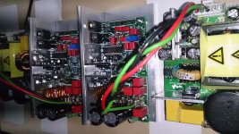
...had a closer look to your build:
Nice!
Starting to feel my mechanical skills are sub average. 😱
One hint regarding safety: In your picture the supply wires comming from the PSU on the left side of the picture are crossing beyond the primary side of the PSU.
Make sure that the wires keep 6mm distance vs the primary side components,
or put the wiring in a thick wall isolation sleeve with at least 0.4mm wall thickness (some types of shrinking tubes can provide this).
5, 6, 7 or 8 turns from mosfets, can't find point on wire with dmm, can't see difference, it's ampboard in center of my picture above🙂 think it was the edge of little mosfet angle but was touching main Lprofile too same height, heatshrink is good idea if I have big enough diameter, have to look, can put some tape on heatsink too, not likely to move by itself but might drop something on it some day 🙂
Will turn PSU's, temp setup with doublesided tape against movement for safety LOL will put some heatshrink around center -V voltage pin too, maybe V+ too, because inductor is close there too jeje
The "problem" inductor board aluminium looks very good to me, the other channel is a little ugglier second little mosfet angle is touching EKS's too (all Frolyt that was the wait for German parts), temperature is low now, but need to rework again maybe, already had to mount 243&244 a little towards future gainboard and shaved off some of little angle mosfetsprofile side that touches main Lprofile, 243 didn't fit freely next to it, but worked instantly 😀
The "problem" inductor board aluminium looks very good to me, the other channel is a little ugglier second little mosfet angle is touching EKS's too (all Frolyt that was the wait for German parts), temperature is low now, but need to rework again maybe, already had to mount 243&244 a little towards future gainboard and shaved off some of little angle mosfetsprofile side that touches main Lprofile, 243 didn't fit freely next to it, but worked instantly 😀
It's definitely a great pleasure to see your amps. 
Glad that you are able to deal with my devilish mechanical construction.
Glad that you are able to deal with my devilish mechanical construction.
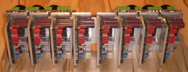
... but worked instantly 😀
Eight in a row - let 'm row. 😀...progress ...
- Home
- Amplifiers
- Class D
- SystemD LiteAmp