Hi Powerflux,
there are exactly two PCB of the main board left over (one has already some pinrows placed). Also two pieces of the gain board are possible.
Sending PCBs will work as a letter with tracking, which limits the shipping costs to 5,60EUR.
Means you could get
2pcs of the main board PCB
and
2pcs of the gain board PCB (version with corrected silk screen)
including shipping for 14,44EUR.
Hi Powerflux,
after I posted my offer, another DIYer adressed to me that he is also interested.
Please let me know if you still want it. I will keep the PCBs reserved for you until Tuesday April 14th 2015, 16h00 (UTC+1, = Berlin time).
After this I will give them to the other DIY enthusiast.
after I posted my offer, another DIYer adressed to me that he is also interested.
Please let me know if you still want it. I will keep the PCBs reserved for you until Tuesday April 14th 2015, 16h00 (UTC+1, = Berlin time).
After this I will give them to the other DIY enthusiast.
Hi Powerflux,
there are exactly two PCB of the main board left over (one has already some pinrows placed). Also two pieces of the gain board are possible.
Sending PCBs will work as a letter with tracking, which limits the shipping costs to 5,60EUR.
Means you could get
2pcs of the main board PCB
and
2pcs of the gain board PCB (version with corrected silk screen)
including shipping for 14,44EUR.
Hi ChocoHolic,
I do want them all so it's a deal! I'll send you a private message later today.
Thank you very much 🙂

🙂
...thanks for posting - yes, it makes me happy to see your build.
How is it running?
But take care and stay with reduced voltage, when running without heat sinks!
...thanks for posting - yes, it makes me happy to see your build.
How is it running?
But take care and stay with reduced voltage, when running without heat sinks!
Dear Markus,
the 4 channel bridged "beast" is now playing every day for some months - excellent sound stage and powerful bass. I love your Lite-Amp.
... waiting for the higher voltage version ... 😉
BR, Toni
the 4 channel bridged "beast" is now playing every day for some months - excellent sound stage and powerful bass. I love your Lite-Amp.
... waiting for the higher voltage version ... 😉
BR, Toni
🙂
...thanks for posting - yes, it makes me happy to see your build.
How is it running?
But take care and stay with reduced voltage, when running without heat sinks!
Hi Marcus
Haven't turned on the beast (will test tomorrow with a temporary install wont trust it without a heatsink)
I will spend some time this weekend and scavenge some heat-sinking before I turn it on. Tony`s metal work is still the best by far, I will do with what I have, a few junkbox heat-sinks will find a good home soon 🙂
I must admit, it is in the waiting queue with low prio.... waiting for the higher voltage version ... 😉
BR, Toni
Hoping to still do it before GaN establishes as standard.
PCIM this year is pretty much GaN-oriented, nevertheless I heard
that it will still take until 2018 before we can expect extensive
GaN portfolios available for everyone like we are used today with silicone.
So there is still a chance that I settle something like a +/-75V version
delivering 500W into 4R unbridged (or 1kW bridged into 8R) before interest
has completely shifted to GaN.
Hi Marcus
Haven't turned on the beast (will test tomorrow with a temporary install wont trust it without a heatsink)

I case of questions just ask here or by PM.
😱
I think I goofed up some where, my amplifier blew a FET and took out the driver.
I followed the getting started guide and determined all the voltages. (with +/- 37V as my supply bus)
1) PIN 1 +5.00V
2) PIN 6 -5.03V
3) C12 11.28V
4) C13 14.28V
5) Check if U1 is inserted
6) Check if U1 is inserted with correct orientation. ;-)
Connected my scope up, no continuous oscillation, just a few bursts of oscillation, I removed the current limiters and one fet heated up and took out the driver. I know I should never have done that.
Well I fixed up the issue as I have fets for my other board, use one of them and replaced the driver IC, with the 100R current limiters, with the new parts fitted, I went over the voltage check list it passed, still no oscillation, nothing at all this time. its probably something very simple im missing but what can it be.
do you have a diode from com to vss to prevent latchup ?, in case the supplies do not come up simultaneously. that is how i fried one irs2092
do you have a diode from com to vss to prevent latchup ?, in case the supplies do not come up simultaneously. that is how i fried one irs2092
hi
there is no such nodes on the original schematic that I can see?, come to think of it, the supply was accidentally still on, when I swop out the resistors.
do you have a diode from com to vss to prevent latchup ?, in case the supplies do not come up simultaneously. that is how i fried one irs2092
Thanks found it, its D3 MBR1100
The issue with Vss being pulled below COM in case of a missing negative power rail is not going to happen in this design, because Vss is derived from the negative power rail. In this design there is no mechanism which would pull Vss more negative than COM.
Nevertheless the additional diode as described by bassreflex will not harm.
Before destroying all power devices:
1: You can run the amp with one halfbridge. No need to have both Q6 and Q7 in place. One of them will already be fine for loads of 4R and higher.
2: Check if the first burn out really killed Q6 and Q7 or just one of them.
Let's start with the first situation. Amp in burst mode.
If all voltages are fine as described, then the remaining typical reasons for this would be:
- Forgotten to remove one of the shorting wires
- A short in the power stage, filter section or output
- Error in the feedback and loop gain network
- Wrong resistor values at OCset or OCset shorted to -40V rail
- Wrong resistor vaules at CSH
In order to understand what happened after you removed the current limitation - please tell what exactly you mean with
...removed the current limiters....
Which component(s) did you change in which way?
Your description that the killed amp now after repair does not even enter burst mode anymore is pointing to hidden defects which you did not repair.
In case you burned the MosFets in a way which also killed the IRS2092, there
is the danger that also one or multiple of the gate drive components have been damaged (R30,R31,R32,R33,R36,R37,D7, D8).
Do they all show correct values?
In order to understand what happened after you removed the current limitation - please tell what exactly you mean with
...removed the current limiters....
Which component(s) did you change in which way?
Hi
The 100R 5W current limiters (which is in series with the +/- 37V supply bus), was removed when burst mode was experienced (which I should never have done in the first place) When I did that the FET blew and took out the driver with it (verified destroyed components HOT IC, 0 ohms drain to source the other FET still seems okay, no shorts, could possibly be leaky not sure)
I will slowly go through your check list and re-check the components.
The issue with Vss being pulled below COM in case of a missing negative power rail is not going to happen in this design, because Vss is derived from the negative power rail. In this design there is no mechanism which would pull Vss more negative than COM.
Nevertheless the additional diode as described by bassreflex will not harm.
Before destroying all power devices:
1: You can run the amp with one halfbridge. No need to have both Q6 and Q7 in place. One of them will already be fine for loads of 4R and higher.
2: Check if the first burn out really killed Q6 and Q7 or just one of them.
Let's start with the first situation. Amp in burst mode.
If all voltages are fine as described, then the remaining typical reasons for this would be:
- Forgotten to remove one of the shorting wires
- A short in the power stage, filter section or output
- Error in the feedback and loop gain network
- Wrong resistor values at OCset or OCset shorted to -40V rail
- Wrong resistor vaules at CSH
In order to understand what happened after you removed the current limitation - please tell what exactly you mean with
...removed the current limiters....
Which component(s) did you change in which way?
Your description that the killed amp now after repair does not even enter burst mode anymore is pointing to hidden defects which you did not repair.
In case you burned the MosFets in a way which also killed the IRS2092, there
is the danger that also one or multiple of the gate drive components have been damaged (R30,R31,R32,R33,R36,R37,D7, D8).
Do they all show correct values?
(R30,R31,R32,R33,R36,R37,D7, D8).
R30 = 7R
R31 = 7R
R32 = 15R
R33 = 15R
R36 = 15R
R37 = 15R
D7 = OK
D8 = OK
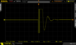
I also set-up the scope to trigger in single shot mode at the output, this is what I got, a short burst, the burst events are frequent every 4 seconds, not sure what this means.
Attachments
Last edited:
Hi
The 100R 5W current limiters (which is in series with the +/- 37V supply bus), was removed when burst mode was experienced (which I should never have done in the first place) When I did that the FET blew and took out the driver with it.
Thanks for this description. It is pointing to an error which either makes the protection of the IRS2092 ineffective or is generally not caught by its protection mechanisms.
...have to think about this, it is an error which did not happen to me during my design phase.
Like all of us, I am trying to keep my amount of building errors low.
So everybody who builds the amp has good chances to make different errors than I did and searching them is more difficult than errors that I already made.
A new search has begun...
Good to see burst mode again.
The switching frequency of the first few periods seems to be pretty low.
More or less close to the filter resonance which will cause high currents and
trigger shut down, however this shut down mechanism also should reliably work without 100R in the rails and with the implemented 4s restart delay it should be save until slow overheating of the MosFets may happen.
The low oscilation frequency is pointing to errors in the feedback and loop gain network (all the components connected between the amp output and pins 3&4 of the IRS2092).
Good to see burst mode again.
The switching frequency of the first few periods seems to be pretty low.
More or less close to the filter resonance which will cause high currents and
trigger shut down, however this shut down mechanism also should reliably work without 100R in the rails and with the implemented 4s restart delay it should be save until slow overheating of the MosFets may happen.
The low oscilation frequency is pointing to errors in the feedback and loop gain network (all the components connected between the amp output and pins 3&4 of the IRS2092).
Thanks for the help thus far, burst was there, I had to enable persistence mode on the scope.
Anyway, I will have now turn to the feedback loop and re-check all the components again, it might just be something very simple like a small solder blob.
blop or bridge..
Will ready a cup of coffee and debug the problem as you recommend. 🙂
Last edited:
Good to see burst mode again.
The switching frequency of the first few periods seems to be pretty low.
More or less close to the filter resonance which will cause high currents and
trigger shut down, however this shut down mechanism also should reliably work without 100R in the rails and with the implemented 4s restart delay it should be save until slow overheating of the MosFets may happen.
The low oscilation frequency is pointing to errors in the feedback and loop gain network (all the components connected between the amp output and pins 3&4 of the IRS2092).
PIN 2 and 3 reads 1 ohm, this is certainly not correct, I will investigate.
- Home
- Amplifiers
- Class D
- SystemD LiteAmp