The power supply goes nutz and current Limit comes flashes on...
Maybe because the supply current has really reached the PSU's limit. For example: 40V/4ohm=10A.
Maybe because the supply current has really reached the PSU's limit. For example: 40V/4ohm=10A.
Not sure what the max Current ratings on those power supplies are. Anyway I added the 100pF (bottom side of the board, sorry
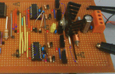
Ok here's the backside of the board (where you can see the high freq 100nF caps this time around).
With Gain Adjustment Pot
http://img43.imageshack.us/img43/9121/dsc00044wz.jpg
Backside of the Board
http://img23.imageshack.us/img23/7386/dsc00045pn.jpg
Maybe it's just my Ears because others say it sounds fine. But to me it looks like the music being played is like High Pass filtered. Can it be the speaker itself or something in my circuit I am missing? Also I haven't yet added the 0.1uF cap between Vdd and ground.
Last edited:
Besides software, do I need any physical hardware to do a FFT test on my Board? Because I've seen around the forums, people showing professional graphs and plots of THD and decibal range and so on and I would like to do the same as well.
I also wanna know what the actual gain of this amplifier is..lol
How can I go about calculating this?
I also wanna know what the actual gain of this amplifier is..lol
How can I go about calculating this?
20uH and 100nF explains the +/-5V residual for me.
Ok I calculated my L and C values based on a 2'nd order filter with a cut-off freq of 100KHZ. So should I use another L and C values then?
Say bring the cut-off down to 30KHZ?
And what magnitude of Residual is good?
The sound input wires or wires from the volume pot can act as an antenna and produce various 'effects'. So, place the 100pF cap between the sound input and the ground, directly on the TL494 pins maybe. This should help you to solve the problems with power current spikes, when you wheeling the volume pot.
Good luck!
I have no Wires on my Pot at all. It's directly connected to the copper tracks. I made the holes just slightly bigger to put the pins through.
Also why add a 100nF cap on my power rail. You've drawn the blue line right under 2 red wires. Which are the input supply to the XOR IC and also the second input to one of the XOR gates.
I meant you need the cap here too. The 12V traces are too far from TO-220 reg here.
I've added this cap today as well. Just got the two 0.1uF caps left now to add between Vdd and ground. No idea how to do so though. I'm a little stuck for space. Looking at soldering it at the bottom again.
Last edited:
Just got the two 0.1uF caps left now to add between Vdd and ground. No idea how to do so though. I'm a little stuck for space. Looking at soldering it at the bottom again.
If you meant to add two 0.1uF caps between Vdd and Vss of IR2110, then make the needed holes in Veroboard a little bit larger, and put both the wire and cap's pin into this.
Attachments
If you meant to add two 0.1uF caps between Vdd and Vss of IR2110, then make the needed holes in Veroboard a little bit larger, and put both the wire and cap's pin into this.
No not like that..lol
I mean I have wires.. The cap has to be close to the Pin right.. But There's wires in the way.
Edit: Oh I see what you mean now
But Wouldn't it just be easier to solder underneath again like the 100pF cap?
Anyway I added the 100pF (bottom side of the board, sorry) and it's resolved my problem. I can Crank the volume all the way up now (Listened to some techno at max volume..lol).

Oh I see what you mean now
But Wouldn't it just be easier to solder underneath again like the 100pF cap?
Do you have forgotten about constraints from your teacher?
Do you have forgotten about constraints from your teacher?He does not like that!

You know what. The hell with it.. I have had more help from here then from him. And I'm a little stuck for space. Soldering Underside seems easier then going to the trouble of drilling a bigger hole and re-soldering the wires and cap.
I'm ok with sacrificing marks for that. The graphs I see I am happy with. Aesthetics are the last thing on my mind at the moment.
Last edited:
Although to my ears the sound I hear is like being High Pass Filtered (Maybe its just me).
The speaker without enclosure sounds as a high pass filtered too...
Also, this can be perceived so because of too much distortions... Just put the 1kHz sine wave into amp, put the 4 Ohm resistor at output and look with the scope at the output (do not forget to post the photo here
Also, please, put the actual schematic (hand painted maybe) here... With the volume pot.
The speaker without enclosure sounds as a high pass filtered too...
Also, this can be perceived so because of too much distortions... Just put the 1kHz sine wave into amp, put the 4 Ohm resistor at output and look with the scope at the output (do not forget to post the photo here).
Also, please, put the actual schematic (hand painted maybe) here... With the volume pot.
I will do that tomorrow along with the 0.1uF capacitors.
Yes I still need to finish up me schematic as well.
I just made this now. So it's crappy but I'll make a proper schematic later.
http://img30.imageshack.us/img30/2245/diagram1s.png
http://img198.imageshack.us/img198/4710/diagram2.png
Edit: I didn't include the High Freq caps. Do I have to add them as well?
http://img30.imageshack.us/img30/2245/diagram1s.png
http://img198.imageshack.us/img198/4710/diagram2.png
Edit: I didn't include the High Freq caps. Do I have to add them as well?
I didn't include the High Freq caps. Do I have to add them as well?
They are the important part of your schematics too
Also, it is not a good idea to remove the cap between pin 16 and Gnd.
 It should be placed as close as possible to the TL494 too...
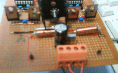
 And I like these two small antennas in the pic below
 But it is better to place them near to the inductors (and cut the Veroboard traces too).
 Attachments
Ok I calculated my L and C values based on a 2'nd order filter with a cut-off freq of 100KHZ. So should I use another L and C values then?
Say bring the cut-off down to 30KHZ?
Yes, the cut-off at 30KHZ will be good. But the usual speaker's impedance differ from nominal at this frequency. So it almost does not makes a sense to calculate the LC values here... Simply use the typical 30uH inductors and 470nF cap.
And what magnitude of Residual is good?
1-2V peak will be good in your project
Also, it is not a good idea to remove the cap between pin 16 and Gnd.It should be placed as close as possible to the TL494 too...

Oh dear. I don't even have a capacitor between Pin 16 and ground. So again another 100nF cap between Pin 16 and ground?
And I like these two small antennas in the pic belowBut it is better to place them near to the inductors (and cut the Veroboard traces too).

That is my test point. They effect my system as well?
Can you explain a bit more on cutting the veroboard traces. where exactly you mean?
Edit: Oh I see you mean cut the copper track right after the Inductor. Unlike now where I just have it going all the way.
Is it ok to connect it from Pin 16 and 13 instead? That's the best I can do.
And LOL your def not gonna be happy about the 3 Pins (Antenna) I have hiding behind that connector.lol. Guess I should move them as well?
Last edited:
Oh by the way. I do not have a 47uF cap from the supply pin of the TL494 to Ground, but a 100nF cap (The blue cap you see on the TL494).
The 47uF cap Ledmania uses seems overkill or am I wrong (As usual -_-).
Because I agree now. I see like an offset in the output PWM from the TL494 that's prob because I'm missing a cap somewhere that I should have placed.
The 47uF cap Ledmania uses seems overkill or am I wrong (As usual -_-).
Because I agree now. I see like an offset in the output PWM from the TL494 that's prob because I'm missing a cap somewhere that I should have placed.
Last edited:
Yes, the cut-off at 30KHZ will be good. But the usual speaker's impedance differ from nominal at this frequency. So it almost does not makes a sense to calculate the LC values here... Simply use the typical 30uH inductors and 470nF cap.
1-2V peak will be good in your project
Will a 5V residual kill performance?
- Status
- This old topic is closed. If you want to reopen this topic, contact a moderator using the "Report Post" button.
- Home
- Amplifiers
- Class D
- Doing a class D Amp project using TL494

