I trigger my scope say rising edge and the falling edge is modulating.
Can you check that the same thing not presented BEFORE the XOR part? I mean, trigger you scope with the rising edge of the PWM signal before XOR part, and check the falling edge modulation. I am pretty sure, that the PWM signal is ALREADY modulated before XOR part... 🙄 The XOR IC itself cannot change the wide of the pulse. It can only have slow rise/falling edges under high capacitance loading.
Also, is your scope triggered properly? Can you provide the wave images here?
Alright I'll double check the PWM waveform. Although from inspection today, the single PWM output was pretty still. It was the PWM coming out of the XOR the was modulating violently.
Aye. I will upload images also when I recheck em after the weekend.
Although a video would be more accurate, to show you the waveform modulating.
40xx CMOS isn't really good enough for this sort of thing, is it? It's never worked well enough for me in anything timing-critical. Try 74HC86. Limited to 5V logic (can't do 15V), but your edges should look much better.
Yep, that chip was far superior in terms of performance in timing. But I'm fed up with all these different voltage rails. I just want to have a single 20V input supply and regulate that down to 12V for the electronic/logic stuff.
I'm happy to sacrifice the performance of the amplifier as a result.
Also the CD4070BE and CD4070BC are the same right?
One's from Texas (BE) and the other one is from FairChild Semiconductor (BC)
Or Have I just pulled off another mistake on my collection of mistakes.
Ok I don't know why. But Having the input coupling capacitor as open circuit makes it seem like the signal is modulating. Moment I put a input music signal in and not play it, it went normal.
I've built my Full Bridge and I am see a +-5V Output after the 3'rd Order LC Filter. Just the Modulation looks funny when you play music, after the LC filter.
I will post graphs very soon with Pics of what I've done as well.
I do Have One Question. Since this a Full-Bridge I do not need a output coupling capacitor right?
I mean I have taken the Duty Cycle to 50% Approx, but I still Don't trust myself. I would like add the output coupling capacitor I used in my Half-Bridge.
I do Have One Question. Since this a Full-Bridge I do not need a output coupling capacitor right?
I mean I have taken the Duty Cycle to 50% Approx, but I still Don't trust myself. I would like add the output coupling capacitor I used in my Half-Bridge.
The coupling capacitor is NOT needed in your Full-Bridge. With duty cycle = 50%, both halves will give the same 50% of the whole voltage, so the speaker will see a zero here... And only when the duty cycle will be modulated, the bridge will be 'disbalanced' and the speaker will see the doubled modulated voltage.
The coupling capacitor is NOT needed in your Full-Bridge. With duty cycle = 50%, both halves will give the same 50% of the whole voltage, so the speaker will see a zero here... And only when the duty cycle will be modulated, the bridge will be 'disbalanced' and the speaker will see the doubled modulated voltage.
Ok Hopefully I have it perfectly at 50% Duty Cycle (Hope So). This is why i saw my Sine Wave go demented the moment it started modulating? Because I saw double modulated voltage?
I'll post the diagrams here tomorrow (hopefully). It'll help you guys to debug my issue more.
(My apologies with the issue in posting schematics here. These scope's take on Compact flash card as input to saving Waveforms.. It's a pain to get the compact Flash Card Reader.)
One other thing was, I saw Ringing at the output, but my FETS are not Hot at all. Warm at worst to say (It's cold-warm'ish). I remember you guys said the aerial effect the power flow track has.
This is what I'm observing right?
Again I'll post waveforms to make it more clear.
I haven't physically hooked the speakers at all yet. The waveforms you will see will be purely the 3'rd filter as the Load. I had the Issue in the past with the Half-bridge where I input the speaker without proper testing first and the speaker disagreed with me, and so did my circuit. So won't be making this mistake again.
Thanks again everyone. All of you have turned this Newb into having a thing for Audio Amps now 😀
Edit: Thanks = 1 ?
Last edited:
Yo.
I have taken the waveforms (They actually look clean this time around, which is wierd. I haven't touched it since yesterday), but I am still waiting on the compact flash reader, before I put it on my USB.
However I do Have a video of it modulating without the speakers (Sorry best I can do for now).
Here's the Full-Bridge switched Waveform (First Half) and then the output seen across the output of the LC filter (Third Order). I am switching it around 195KHz. The Voltage Rails are +-20V for the switched Waveform and +-5V for the LC filtered Output.
http://www.youtube.com/watch?v=P4SY5xd6_0k
I saw a couple of effects today that I am a little nervous about.
Firstly and mainly, when I increase the volume adjustment potentiometer all the way up, using the circuit that Ledmania had posted a few pages back. The power supply goes nutz and current Limit comes flashes on and also the voltage meter flicks up and down. I do not understand why.
However it works fine until a certain limit before it goes nuts. Should I decrease the Pot Value or increase the Pot I am Using?
The Second thing, every time I turn on the power supply. I hear a big "POP" from the speaker. How can I Eliminate this?
However I do Have a video of it modulating without the speakers (Sorry best I can do for now).
The video is beautiful. 🙂 And I would say the output is NOT modulated... The pulse widths are constant (even when flicking). The WHOLE wave seems to be shifted for short times. But it is more the synchronisation problem in your scope, I think. 🙄
Firstly and mainly, when I increase the volume adjustment potentiometer all the way up, using the circuit that Ledmania had posted a few pages back. The power supply goes nutz and current Limit comes flashes on and also the voltage meter flicks up and down. I do not understand why.
The power supply flicking can be caused by unstable output stage switching frequency. The frequency is simply too high for short times (this causes the mosfets to be opened both). This can be caused by 'switching' of your schematic into 'self oscillating' mode because of parasitic capacitances or EMI. Add more decoupling caps to your power rails on the board. Add a small ceramic cap (saying 100pf) between TL494's input and ground, but so close as possible to this IC.
The Second thing, every time I turn on the power supply. I hear a big "POP" from the speaker. How can I Eliminate this?
I would say, this is unavoidable in your schematic. This happens because of the input capacitor charging. The input before this cap is 'grounded' via the volume pot, and the other side should have 2.5 Volts for the duty cycle = 50%. When you turn on your amp, this input cap is discharged (has 0V around it), and this makes your duty cycle unequal to 50% for short time (till the cap is charged), and this causes this "POP" effect.
Also, I wonder, why you have +-5V residual. This is a little bit too much...
Please, send the photos of your current Veroboard. Both sides. This will simplify all things a lot. 😉
Last edited:
The video is beautiful. 🙂 And I would say the output is NOT modulated... The pulse widths are constant (even when flicking). The WHOLE wave seems to be shifted for short times. But it is more the synchronisation problem in your scope, I think. 🙄
Well, looked at the video one more time... Indeed, the output is modulated... Does it happens without input signal? Do you rotating the volume pot at this moment? 🙄 And generally, the modulation seems to be fully OK 🙂
Well, looked at the video one more time... Indeed, the output is modulated... Does it happens without input signal? Do you rotating the volume pot at this moment? 🙄 And generally, the modulation seems to be fully OK 🙂
Nah Mate only happens when I play music now. And also when I turn the pot to higher Volumes. When I fully turn the Pot down, it does not modulate.
The power supply flicking can be caused by unstable output stage switching frequency. The frequency is simply too high for short times (this causes the mosfets to be opened both). This can be caused by 'switching' of your schematic into 'self oscillating' mode because of parasitic capacitances or EMI. Add more decoupling caps to your power rails on the board. Add a small ceramic cap (saying 100pf) between TL494's input and ground, but so close as possible to this IC.
I have a 100nF cap between the Supply and the common ground. I tried my best to keep it close to the chip as possible.
So adding another 470uF capacitor in parallel with the 470uF I already should solve the problem? I also have a 100nF high freq cap in parallel to the 470uF Bus Cap.
The 5V ref voltage pin on the TL494 also has a capacitor as well just like in Ledmania's Circuit.
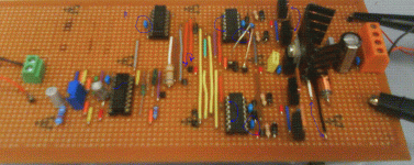
Here's a pictures of my veroboard design.
http://img225.imageshack.us/img225/5331/dsc00037q.jpg
I couldn't avoid the long wires between the XOR gate and the second Gate Driver. It was Either that or long wires between the gate driver and FETS.
Ahh shoot. It's the pic taken before the Volume Pot. I'll take it with the volume Pot tomorrow.
Last edited:
I have a 100nF cap between the Supply and the common ground. I tried my best to keep it close to the chip as possible.
This is good. But I meant the cap on the audio input of the TL494. The sound input wires or wires from the volume pot can act as an antenna and produce various 'effects'. So, place the 100pF cap between the sound input and the ground, directly on the TL494 pins maybe. This should help you to solve the problems with power current spikes, when you wheeling the volume pot.
Ahh shoot. It's the pic taken before the Volume Pot. I'll take it with the volume Pot tomorrow.
Well, looks good 😉
You have NOT an 3'rd order LC filter. Actually, there are two 2'nd order filters. 😉 Also, I slowly understand now, why you had such a 'huge' residual at the output (+/-5V): you have a relatively low switching frequency (196kHz) and a relatively low inductances in your LC filter (20uH ?). And the cap in the output filter is not so big too, as I see it in the photo (is it here at all? 😀). And we have not seen any ringing in this residual too! This is good too.
Instead of placing of a 'huge' 1000 uF capacitors at the power connector, it is much better to place small caps (0.1uF) around the board (near to each IC and around each pair of mosfets!).
Please, do not forget to post the back side photo here too! 😉
Good luck! 😉
This is good. But I meant the cap on the audio input of the TL494. The sound input wires or wires from the volume pot can act as an antenna and produce various 'effects'. So, place the 100pF cap between the sound input and the ground, directly on the TL494 pins maybe. This should help you to solve the problems with power current spikes, when you wheeling the volume pot.
Hmm Not sure if i can put right on the PWM chip. Because the Music input is the green connector you see. Again with the latest photo I'll upload tomorrow it'll become more clear.
So throwing a 100pF cap here would minimize my problem and i can punch the pot all the way up without the power supply going insane?
By close to the TL494 as possible. You mean Which Pin? Pin 16? Which is the Pin the Music goes to Ultimately. So between Pin 16 and ground is what your saying?
I'm a little lost for space if that's how it should be. >_<
Is it ok to just chuck the 100pF cap close to the music rails?
you have a relatively low switching frequency (196kHz)
196KHz is low? 😱
And the cap in the output filter is not so big too, as I see it in the photo (is it here at all? ).
yep there is a 100nF capacitor in parallel with the speaker. And the two inductors are connected to either leg of the capacitor. It's silver thing you see behind the bus capacitor.
it is much better to place small caps (0.1uF) around the board (near to each IC and around each pair of mosfets!).
That's what the 100nF blue capacitors are there for. You see them on the TL494 and the XOR chip. Also each half bridge has a 100nF cap connected between drain of high side mosfet and source of low side mosfet.
Edit: Ahh crap, bad view. You don't see the high freq caps on each pair of MOSFETS. But I have added them.
Again I'll post picture of the latest model to make it more clear of what I am doing at the Input.
Last edited:
So all I am missing then is the 100pF cap between the Input of the Music signal and Ground?
No. It is highly recommended to place the 0.1uF caps where it is shown with blue arrows in the picture below too.
The 100pF cap should be placed directly between the Pin 7 (Gnd) and Pin 15 of TL494 on your schematic (this is NOT shown with blue arrows in the picture below).
Attachments
Wait what? Add 100nF caps from 12V Vdd pin to Vss pin?
Also why add a 100nF cap on my power rail. You've drawn the blue line right under 2 red wires. Which are the input supply to the XOR IC and also the second input to one of the XOR gates.
Again bad angle but I do have a high freq 100nF cap from drain to source on each pair of MOSFETS.
I couldn't directly connect the 100nF cap from the supply pin of the chip to the ground. So I've just taken it from Supply Pin to the common ground (Best I can do).
The teacher doesn't want me to solder bits underneath. He want's it all on the top.
And Alright I will add a 100pF cap from Pin 15 to the ground Pin.
Last edited:
So throwing a 100pF cap here would minimize my problem and i can punch the pot all the way up without the power supply going insane?
Yes, it should do so 😉
By close to the TL494 as possible. You mean Which Pin? Pin 16? Which is the Pin the Music goes to Ultimately. So between Pin 16 and ground is what your saying?
I'm a little lost for space if that's how it should be. >_<
You do not kow where in your schematic the music goes into? In which pin? 🙄 It is Pin 15, according to your old schematic: (http://img216.imageshack.us/img216/617/schematic.png)
Is it ok to just chuck the 100pF cap close to the music rails?
No. In the case with Veroboard design it is needed to be mounted directly on the TL494 pins.
196KHz is low? 😱
Yes, generaly it is low. But it is ok for your prototype. 😉
yep there is a 100nF capacitor in parallel with the speaker. And the two inductors are connected to either leg of the capacitor. It's silver thing you see behind the bus capacitor.
20uH and 100nF explains the +/-5V residual for me.
You need to understand the simple thing. Each piece of wire or Veroboard trace is simultaneously an inductor, an antenna, an capacitance connection to each other points in your schematic, etc. These parasitics cannot be avoided, but only minimized with a good PCB layout or a ground plane. So you need to shunt all your antennas and power connections properly. Generally, it is even more complex to do on Veroboard, than developing of a good PCB. 🙁 But in your project it is not need to have it all ideal. It should work with my recommendations too, I think... 🙄
Wait what? Add 100nF caps from 12V Vdd pin to Vss pin?
Yes! This will clear the input power supply of IR2110. The HF cap after the TO-220 reg is too far from each IC.
Also why add a 100nF cap on my power rail. You've drawn the blue line right under 2 red wires. Which are the input supply to the XOR IC and also the second input to one of the XOR gates.
I meant you need the cap here too. The 12V traces are too far from TO-220 reg here.
Again bad angle but I do have a high freq 100nF cap from drain to source on each pair of MOSFETS.
Well done! 😉
I couldn't directly connect the 100nF cap from the supply pin of the chip to the ground. So I've just taken it from Supply Pin to the common ground (Best I can do).
The teacher doesn't want me to solder bits underneath. He want's it all on the top.
Connect it OVER the IC (not under) 😀
[/QUOTE]And Alright I will add a 100pF cap from Pin 15 to the ground Pin.
ok!
Ok I already have a 100nF cap in parallel with my Bus Cap. You can a little blue guy right behind the fat bus cap.
So I'll add another 100nF where you drew the Red Line, since as you say the 12V line is literally drawn out and the HF cap is too far away from it.
So I'll add another 100nF where you drew the Red Line, since as you say the 12V line is literally drawn out and the HF cap is too far away from it.
- Status
- Not open for further replies.
- Home
- Amplifiers
- Class D
- Doing a class D Amp project using TL494