Pardon my ignorance... I see a lot of care to insulate the bolt + heatsink from the amp's power chip, as often the case.
I always wondered how this worked inside the chip's hole: for sure the bolt must be touching when passing through - how is that insulated?
Many thanks and sorry for the basic question, learning on how to build amps!
Claude
Yes, as Astromo pointed out they are called insulating bushing or “shoulder washers”. Typically nylon but I have seen Teflon as well.
For example:
https://www.amazon.com/dp/B00KV6P828/ref=cm_sw_r_cp_api_glc_fabc_JRX.FbT4H9MM1
I am using ceramic insulator pad but silicone spacer is probably fine as the thermal flux is not huge.
Last edited:
Looks good X. Do you know the model number of those heatsinks? I’m thinking they might work well for a MoFo
Indeed, I bought these for use in Class A like a MoFo. They are Dell T7500 LGA1366 CPU heatsinks. Typically surplus circa $20 a pair. They are nice and heavy. With a Noctua fan can easily handle 150w is my guess.
Dell Precision T3500 T5500 T7500 LGA 1366 Processor Heatsink 0T021F LOT OF 2 | eBay
The TDA7293 Xmas Amp is now playing music! ...
This is really exciting. Planning and building amps makes me feel like a kid looking at the Christmas catalogs.
Great! I'm eagerly awaiting the boards now! Btw, is there some way elaborated already to provide our postage adresses to you and to enable you to calculate the s/h fee?
Best regards!
Now that we have two verification builds out of the way, we are ready to proceed to the address and shipment payment phase. The moderators told me to start a thread in the Swap Meet forum to do this and keep this thread for technical discussions. I’ll start that shortly. Since I am not allowed to use Etsy for handling the logistics of auto calculating shipment, I think the easiest thing for me is to charge approx flat rates similar to the past to cover PayPal fees, padded envelopes, and shipping labels.
Probably $5 in US, $8 Canada, and $15 everywhere else.
Here is the link to the giveaway logistics thread in the Swap Meet forum.
https://www.diyaudio.com/forums/swa...3-xmas-amp-jhofland-giveaway.html#post6487628
https://www.diyaudio.com/forums/swa...3-xmas-amp-jhofland-giveaway.html#post6487628
Final Gerbers, Schematics, and BOM
Here are the final design files with the following changes:
1. Isolate the mounting bolt pads from the ground plane, except the top right bolt is connected to the ground via a ground loop breaker (opposed diodes, 10R resistor, and 100nF film cap, all in parallel)
2. Add third set of optional pads for Wima 4.7uF 250v MKP film cap at C1
3. Add 100k resistor to input pin upstream of input coupling cap.
4. Update BOM to show 47k5 resistor for R15 to allow DC servo to work properly.
New and final board layout (107mm x 65mm):
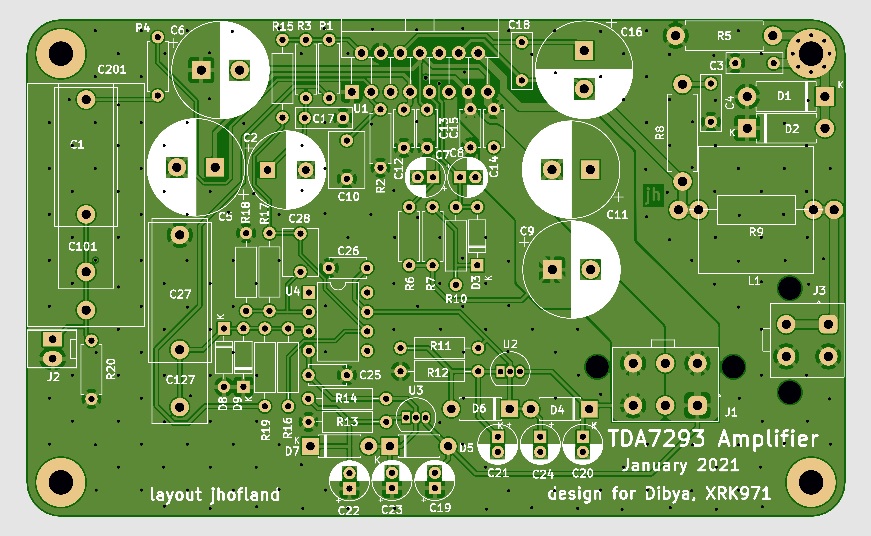
Attachments

I have been listening to the Xmas amp for two days now. Both on my 10F/RS225 TLs and my Rockville 2-way bookshelf speakers. It’s a great sounding amp. Smooth and very enjoyable. Can put out some power when needed. It’s quite amazing how easy it is to build. The startup is also very painless. Not a white knuckle experience like firing up some amps for the first time. With DC servo the offset is rock steady near 4mV no matter what.
I’m really enjoying mine!
I’m really enjoying mine!
Hi Folks,
Sixto measured a parallel Chinese/eBay TDA7293 and got some nice results. It has dominant second order distortion as I suspected it would as a result of the quasi complimentary output stage. Pretty low distortion figure at 0.0027% THD.
@Sixto, I did not catch what condition (Volts rms and ohms load)?
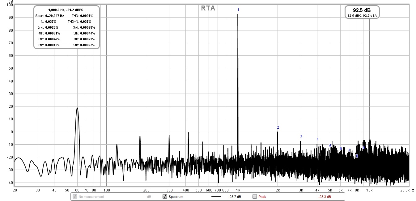
I think it is great that this chip is getting some love here. I have spent more hours than I would ever admit searching for good TDA7293 boards. I tracked down one in Japan that is waiting at a forwarding service but will cost me nearly what these two boards and all the components are going to cost me to get it actually delivered.
I stumbled on this thread once all the boards were claimed and then got lucky when a couple cancelled.
I really appreciate all the work that went into this; including the great BOM.
I stumbled on this thread once all the boards were claimed and then got lucky when a couple cancelled.
I really appreciate all the work that went into this; including the great BOM.
Hi Folks,
Pretty low distortion figure at 0.0027% THD.
@Sixto, I did not catch what condition (Volts rms and ohms load)?
Hi X, I got 2.87 volts at the meter using an 8-ohm 100 watt resistor for the load. I willl see if I can run a sweep of multiple frequencies and also run 2 resistors in parallel for 4 ohm load. Still learning how to use this feature of REW.
Six
I just did a test on the Xmas amp and it beats the ST data sheet. Seems like design choices and good layout makes a difference. I am getting -65dB of 60Hz mains showing up but it’s not that audible unless I press my ear to the cone. This might just be par for the course for a linear trafo with straight caps.
Test setup: Akitika 2ppm 1kHz oscillator, Focusrite 2i4 interface with XLR input using balanced 10:1 divider and 4.7uF balanced MKP coupling caps, EBG 10ohm 300w non-inductive resistor, Vrms measured with Fluke 115 true RMS meter.
I am getting 0.0017% THD at 2.85vrms into 10ohm. 0.0014% at 8vrms, but becomes less and less H2 dominant as power goes up. This is one of the few H2 dominant chip amps though.
Here is 2.85vrms:

Here is 8vrms:

Here is 10vrms:

Looks like a nice amp based on measurements alone. Listening confirms this as the sound is very natural and fatigue free.
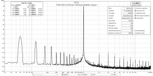
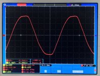
Edit - I suspected that my power company is giving me some dirty AC that’s not even close to sine wave. My oscope proves that it looks like a bread loaf and this generates a lot of harmonics from the 60Hz. Very tough to clean up unless one uses more CRC or a cap Mx. I know my cap Mx PSU can make all this into 1mV ripple at the amp. Here is what the mains looks like:

Test setup: Akitika 2ppm 1kHz oscillator, Focusrite 2i4 interface with XLR input using balanced 10:1 divider and 4.7uF balanced MKP coupling caps, EBG 10ohm 300w non-inductive resistor, Vrms measured with Fluke 115 true RMS meter.
I am getting 0.0017% THD at 2.85vrms into 10ohm. 0.0014% at 8vrms, but becomes less and less H2 dominant as power goes up. This is one of the few H2 dominant chip amps though.
Here is 2.85vrms:
Here is 8vrms:
Here is 10vrms:
Looks like a nice amp based on measurements alone. Listening confirms this as the sound is very natural and fatigue free.
Edit - I suspected that my power company is giving me some dirty AC that’s not even close to sine wave. My oscope proves that it looks like a bread loaf and this generates a lot of harmonics from the 60Hz. Very tough to clean up unless one uses more CRC or a cap Mx. I know my cap Mx PSU can make all this into 1mV ripple at the amp. Here is what the mains looks like:
Attachments

Last edited:
Some improvements in Measurment Setup
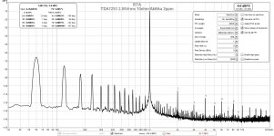
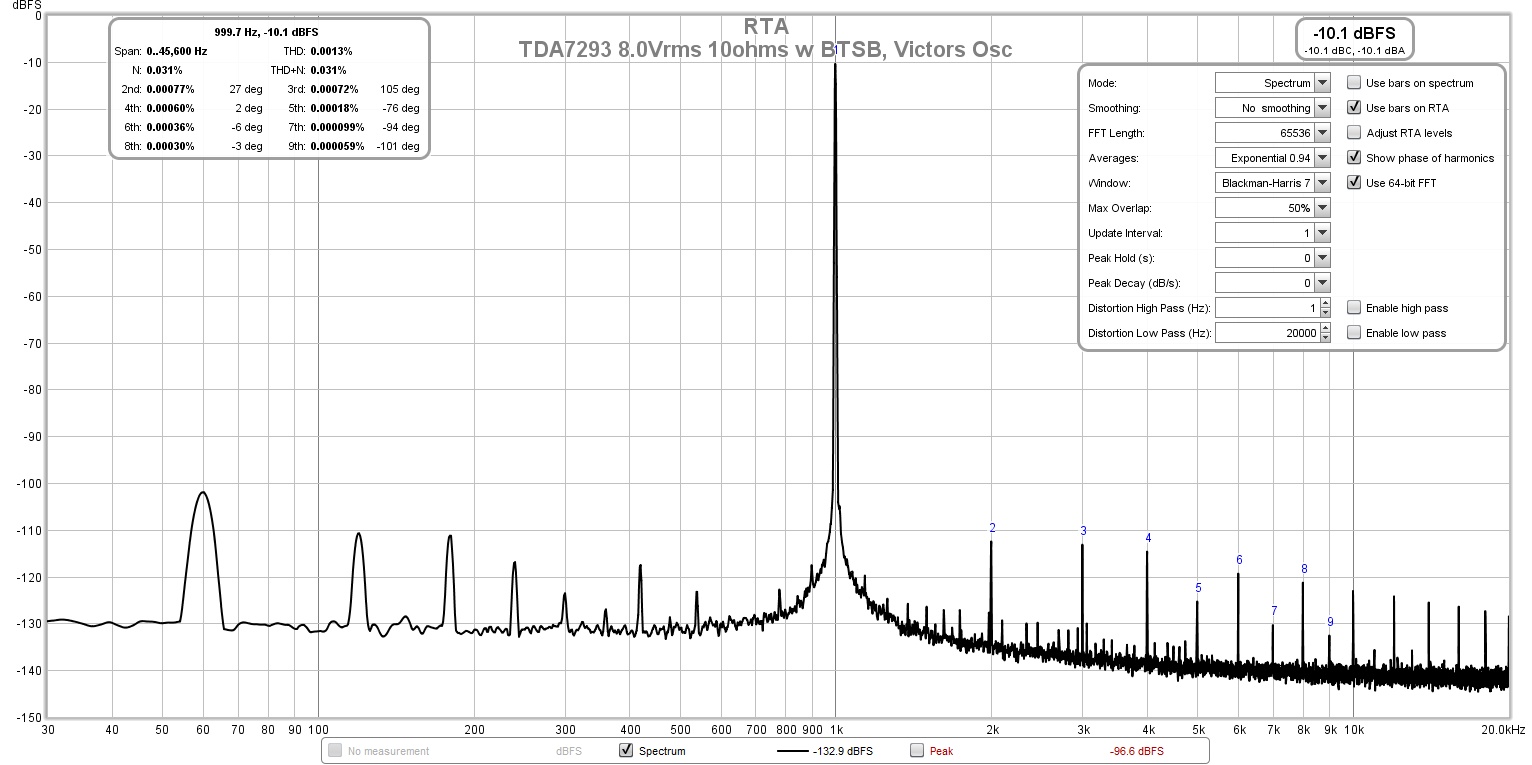
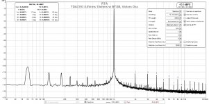
After trying to figure out where all that mains noise was coming from, it seems that adding a OPA1656/LME49724 balanced/SE buffer (which has a 5kV isolated DC/DC converter for making the +/-12v rails) between the source and amp, and grounding the buffer's on-board GLB to earth ground helped things. For good measure, I also switched to Victor's ppb 1kHz oscillator. Things look better now and it would appear that I had a small ground loop somewhere that is now broken by the buffer. The 60Hz peak is about -93dB now, very acceptable result as that is basically same as noise floor of CD format. Also, the higher order harmonics of the 60Hz seem to also be controlled. For a typical 8Vrms into 10ohm case, the THD is now 0.0013% and H2 and H3 are about the same but higher orders are monotonically descending:
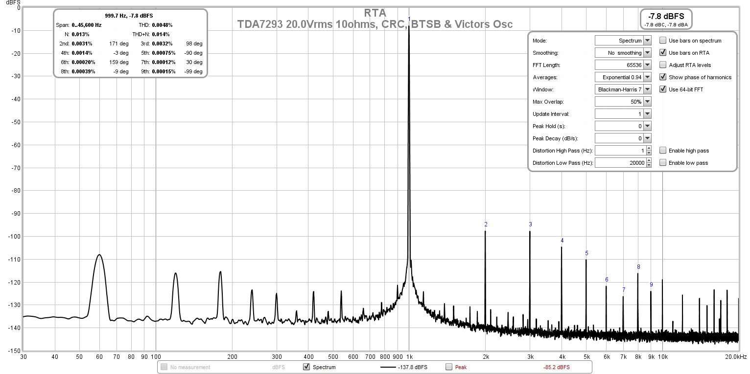
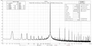
For the 40Wrms case of 20.0Vrms into 10ohms, we get a very respectable 0.0048% THD, mildly 3rd order dominant, but still with monotonically descending higher order distortion:
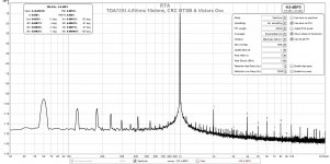
And for the low power 4W case, the amp seems devoid of odd order harmonics for a very sweet sound. If you listen at lower levels or with sensitive full range drivers, you will be in a for melodious tube-amp like treat but with lower overal distortion levels:

Glad I found the ground loop - it really helped to show what a great little chip amp the TDA7293 is. I think these measurements will translate to an amp that you will find sounds neutral, natural, and very non fatiguing to listen to. All this confirms why Dibya thought that this particular chip deserves some attention vs how much has been paid to LM3886 and LM1875. Those are third order dominant harmonic distortion chips I think. I should mention that I converted the PSU to a CRC with addition of a 0.1ohm KOA BPR 5W resistor, but it did not change the noise from ground loop issue much. Both plots above used the CRC version of the PSU.
After trying to figure out where all that mains noise was coming from, it seems that adding a OPA1656/LME49724 balanced/SE buffer (which has a 5kV isolated DC/DC converter for making the +/-12v rails) between the source and amp, and grounding the buffer's on-board GLB to earth ground helped things. For good measure, I also switched to Victor's ppb 1kHz oscillator. Things look better now and it would appear that I had a small ground loop somewhere that is now broken by the buffer. The 60Hz peak is about -93dB now, very acceptable result as that is basically same as noise floor of CD format. Also, the higher order harmonics of the 60Hz seem to also be controlled. For a typical 8Vrms into 10ohm case, the THD is now 0.0013% and H2 and H3 are about the same but higher orders are monotonically descending:
For the 40Wrms case of 20.0Vrms into 10ohms, we get a very respectable 0.0048% THD, mildly 3rd order dominant, but still with monotonically descending higher order distortion:
And for the low power 4W case, the amp seems devoid of odd order harmonics for a very sweet sound. If you listen at lower levels or with sensitive full range drivers, you will be in a for melodious tube-amp like treat but with lower overal distortion levels:
Glad I found the ground loop - it really helped to show what a great little chip amp the TDA7293 is. I think these measurements will translate to an amp that you will find sounds neutral, natural, and very non fatiguing to listen to. All this confirms why Dibya thought that this particular chip deserves some attention vs how much has been paid to LM3886 and LM1875. Those are third order dominant harmonic distortion chips I think. I should mention that I converted the PSU to a CRC with addition of a 0.1ohm KOA BPR 5W resistor, but it did not change the noise from ground loop issue much. Both plots above used the CRC version of the PSU.
Attachments
Last edited:
Hi X,
Moreover TDA7293 datasheet played a bad role, In Datasheet schematic, it has a cutoff of 23Hz and used 470nf input cap , the usual complain of bad bass came. Bootstrap was undersized , and supply bypass was oversized which made the IC to oscillate in 10Mhz range.
It doesn't seem Engineering team wrote the datasheet.
I wanted to change it , the ic that people hated is best Class AB Chip amp.
Fascinating!
Hi X, would you share more details (photo/schematic?)on how you reduced the mains noise please? I am not familiar with this trick.🙂
Thanks! Six
Hi X, would you share more details (photo/schematic?)on how you reduced the mains noise please? I am not familiar with this trick.🙂
Thanks! Six
After trying to figure out where all that mains noise was coming from, it seems that adding a OPA1656/LME49724 balanced/SE buffer (which has a 5kV isolated DC/DC converter for making the +/-12v rails) between the source and amp, and grounding the buffer's on-board GLB to earth ground helped things.
.
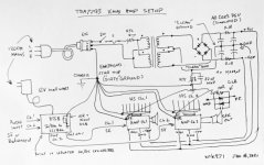
It’s not a trick but a fortunate case that adding a buffer in between my signal source and amp cleaned things up. The buffer has a ground loop breaker to isolate dirty vs clean ground (as do all the other circuits). The buffer happens to have its own separate wall power supply and an isolated DCDC step up dual rail PSU (Murata). Here is sketch of my setup.

Drawing doesn’t show individual wires for PSU to each amp (ran out of room in drawing). This needs to be done for clean star ground.
The important things to keep in mind when wiring up an amp’s power supply and connections and grounding scheme:
Make sure that all connections to ground are deliberate and not accidental or willy nilly. That is, be sure to define “clean ground” or 0V analog PSU reference and signal 0v and “dirty ground” that is the chassis, mains earth ground from wall plug, and heatsink ground, etc.
All connections between clean and dirty must be made through a ground loop breaker (GLB). Each amp board has one on the top right corner screw mounting boss. The All Cee’s PSU has one too as does the buffer board.
All connections from the GLBs must come to a central hub for a star ground topology.
All connections for clean ground must come to a star hub for the 0v GND - which usually resides on the PSU board. In this case, the All Cee’s PSU has 5 spade connectors for this purpose.
Be careful to ensure that the chip amp is insulated from the heatsink with thermal spacer that is non conductive. Make sure that RCA jacks are insulated from the chassis panel. The negative on RCA should only connect to the amp signal input terminal.
Follow these tips and you will most likely end up with a quiet amp.
Attachments
Last edited:
Hi X,
Moreover TDA7293 datasheet played a bad role, In Datasheet schematic, it has a cutoff of 23Hz and used 470nf input cap , the usual complain of bad bass came. Bootstrap was undersized , and supply bypass was oversized which made the IC to oscillate in 10Mhz range.
It doesn't seem Engineering team wrote the datasheet.
I wanted to change it , the ic that people hated is best Class AB Chip amp.
Well, best is hard to define as some people like third harmonic dominant amps - they say it sounds more detailed, etc. So playing at lower volumes will give a very pleasing sweet sound indeed. Pushed hard, it still sounds controlled and respectable without fatigue.
For comparison, here is 43W into 8ohms from a standard eBay LM3886 as measured by Tomchr in another thread:
Last edited:
Hi All,
Ready to put in an order with Mouser. Just a couple of quick questions.
1. Using C201 & C127 covers all the requirements of using C1, C101, and C27, Correct?
2. I have air core inductors that are 2.5uH. Are these OK to use in place of 1.0uH. I can trim them down if 1.0uH is absolutely required.
X, no problem with PP fees. My pleasure.
MM
Hi Myles,
Yes, those are just optional pads for different sizes of caps. Select only one and you are good to go. The air core you have is fine - probably reduce number of windings in half and should be ok. Are they 18ga magnet wire?
Yes, those are just optional pads for different sizes of caps. Select only one and you are good to go. The air core you have is fine - probably reduce number of windings in half and should be ok. Are they 18ga magnet wire?
Hi X,
Calipered to 0.05" = 1.27mm = 16 awg wire. This is the largest it would be.
18 awg is close to 0.04" or 1.016mm
In real world, the inductor legs fit into the Mosfet holes on the FH9 and fit very sloppily in the smallest holes where the large inductor sits on the FH9.
I may have to sandpaper/grind the legs a bit if they do not fit in Xmas pcb or wind some new ones.
MM
- Home
- Amplifiers
- Chip Amps
- Xmas Amp - Dibya's TDA7293 by Jhofland