
Hey folks, yes C17 and C2 should have been DNP and jumpered if implementing DC servo. I had gone full-robo populate mode. Later realizing my error so I removed just C2. Bypassed it with a jumper. I left C17 as vestigial because I did not want to mess with removing a part so close to the chip pins. It’s kind of tight there and I am using a fat 3mm wide chisel tip iron.
You guys need to give Vunce some slack on his re-purposed inductors. No inductor shaming allowed! 🙂 He had no more magnet wire on hand. I think 1uH inductors could be done using nice 30A WE or CoilCraft SMT in the future?
You guys need to give Vunce some slack on his re-purposed inductors. No inductor shaming allowed! 🙂 He had no more magnet wire on hand. I think 1uH inductors could be done using nice 30A WE or CoilCraft SMT in the future?
Last edited:
maybe i missed that information..sorry..why is the C28 shorted/not used?
From post 1:
Note that if populating the DC servo, C17 and C2 should be replaced with jumpers. The on-board voltage regulators are +/-40v max rails so please keep that in mind when choosing the PSU.
It’s actually C2. And either can be shorted. I left C17 (accidentally populated) since it doesn’t matter once one is shorted.
Nice X! A lot sexier (with those fancy green inductors) than Vunce's build, which seem to be missing some components. 😀
Waiting in anticipation for listening impressions...
He is using Zener Power Supply.
Here is a 1uH 27A shielded inductor. Should be easy to hand solder conventionally despite being “SMT”. Very compact and saves us from hand winding magnet wire. Lazy people like me just click and buy! Plus is tools way cool. 🙂
https://www.mouser.com/ProductDetail/Coilcraft/SER1590-102MLB/?qs=VJjuEbE9QBPTtBRZHY%2BH1w==

So a couple of final edits on board that I will request from jhofland:
1. Electrically isolate the remaining 3 bolt holes from ground.
2. Add more room for bigger input cap to allow up to 4.7uF to bring F3 to 1.6Hz.
3. Add SMT pads for the above 1uH 27A shielded inductor as optional to the side of the existing hand wound one.
4. Maybe an LED power on indicator would be good.
https://www.mouser.com/ProductDetail/Coilcraft/SER1590-102MLB/?qs=VJjuEbE9QBPTtBRZHY%2BH1w==
So a couple of final edits on board that I will request from jhofland:
1. Electrically isolate the remaining 3 bolt holes from ground.
2. Add more room for bigger input cap to allow up to 4.7uF to bring F3 to 1.6Hz.
3. Add SMT pads for the above 1uH 27A shielded inductor as optional to the side of the existing hand wound one.
4. Maybe an LED power on indicator would be good.
Last edited:
Hi X,
If you are lazy then what will tell about people like me then? I am too lazy to click the link.
Is that a iron core inductor?
If you are lazy then what will tell about people like me then? I am too lazy to click the link.
Is that a iron core inductor?
Ferrite core. Despite not being air core, should not cause a problem with distortion as currents are way inside the linear range as it is 27A rated. Of course, folks are free to hand wind $0.20 worth of 18ga magnet wire to do the job.
Edit: on second thought this is a budget giveaway amp build and folks should probably wind their own inductors.
The only change needed is to electrically isolate the bolt holes from ground except for the one with a GLB.
Edit: on second thought this is a budget giveaway amp build and folks should probably wind their own inductors.
The only change needed is to electrically isolate the bolt holes from ground except for the one with a GLB.
Last edited:
I plan to use an Academy Audio VCU Muses volume control in front of my amps; it requires +/-15V @ 10mA and the obvious thing would seem to be to tap this off from the DC servo supply on one of the amp boards - anyone see a downside?
You should be fine if you only need 10mA of +/-15v for your volume controller. It’s actually a nice regulated supply on the board.
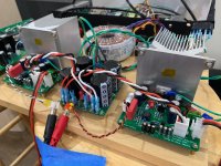
The TDA7293 Xmas Amp is now playing music! The drill and tap operations into these Dell solid aluminum heatsinks was very easy. Making 18 wire assemlbies takes a lot longer than you think. The 250VA 25v trafo is giving me +/-36.0v at the amp. I am testing with Focusrite 2i4 driving an Aksa Lender preamp, which then drives the TDA7293. I am using my 10F/RS225 FAST speakers. After an hour of playing moderate levels, the heatsinks are registering 38 deg C. Just barely warm.
Only listening to a few songs, but so far so good. Amp sounds very nice.
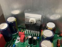
Mounting the chipamp to the heatsink using a ceramic spacer pad and thermal paste:

Bench testing to make sure no smoke or explosions. DC offset is about 4mV to 5mV. When amp is first turned on, DC offset is about 11mV and then quickly settles to 4mV:

Full listening test with main rig comprised of Focusrire 2i4 driving Aksa Lender preamp (with SMT daughterboard) driving TDA7293, driving 10F/RS225 FAST TL speakers:

Closeup of the setup:

So far a very smooth sounding amp. Powering my speakers nicely.
Thank you to Jhofland for another excellent design and layout!
Only listening to a few songs, but so far so good. Amp sounds very nice.
Mounting the chipamp to the heatsink using a ceramic spacer pad and thermal paste:
Bench testing to make sure no smoke or explosions. DC offset is about 4mV to 5mV. When amp is first turned on, DC offset is about 11mV and then quickly settles to 4mV:
Full listening test with main rig comprised of Focusrire 2i4 driving Aksa Lender preamp (with SMT daughterboard) driving TDA7293, driving 10F/RS225 FAST TL speakers:
Closeup of the setup:
So far a very smooth sounding amp. Powering my speakers nicely.
Thank you to Jhofland for another excellent design and layout!
Attachments


Last edited:
Good stuff, thanks for the update and all the work you guys have been putting in. 
I like your final board update list; this looks like it will be a really nice project.
I like your final board update list; this looks like it will be a really nice project.
Thanks NB!
It was a team effort and I forgot to thank Dibya for the original inspiration to make this amp. Also would like to thank Vunce for making the first verification build. Having two verification builds will really clean the project up for a nice build experience.
It was a team effort and I forgot to thank Dibya for the original inspiration to make this amp. Also would like to thank Vunce for making the first verification build. Having two verification builds will really clean the project up for a nice build experience.
Pardon my ignorance... I see a lot of care to insulate the bolt + heatsink from the amp's power chip, as often the case.
I always wondered how this worked inside the chip's hole: for sure the bolt must be touching when passing through - how is that insulated?
Many thanks and sorry for the basic question, learning on how to build amps!
Claude
I always wondered how this worked inside the chip's hole: for sure the bolt must be touching when passing through - how is that insulated?
Many thanks and sorry for the basic question, learning on how to build amps!
Claude
Quick reply to ClaudeG - look out for an isulated insert that the bolt slides through. I think you'll find that you're not looking at a simple washer.
Check here, Figure 2:
http://aosmd.com/res/application_notes/package/AN101_TO220_Guidelines.pdf
Look for "Insulating Bush".
http://aosmd.com/res/application_notes/package/AN101_TO220_Guidelines.pdf
Look for "Insulating Bush".
Great thanks Astromo, very nice and useful document!
Might be of some use to me in the very near future 🙂
Have a nice day
Claude
Might be of some use to me in the very near future 🙂
Have a nice day
Claude
Looks good X. Do you know the model number of those heatsinks? I’m thinking they might work well for a MoFo
Great! I'm eagerly awaiting the boards now! Btw, is there some way elaborated already to provide our postage adresses to you and to enable you to calculate the s/h fee?
Best regards!
Best regards!
- Home
- Amplifiers
- Chip Amps
- Xmas Amp - Dibya's TDA7293 by Jhofland