Maybe you missed my post #398, where I showed how Linn paralleled two TDA1514A in the Majik, and discussed this.
Many thanks for the reminder. I recall having seen the circuit but did not recall the name Linn connected to it.
TDA1514 (I have some somewhere), gain matching adjustment and DC-servo for the off-set.
From the days where England was a part of Europe and very well established in audio. Now it has taken to the sea.............


The heavy duty version!
I have also heavy duty on my shelve, but I start with jellybeans first...

I have also heavy duty on my shelve, but I start with jellybeans first...
Evidently with Lordi and Nightwish. Actually I like Nightwish, Lordi less.............
Many thanks for the reminder. I recall having seen the circuit but did not recall the name Linn connected to it.
TDA1514 (I have some somewhere), gain matching adjustment and DC-servo for the off-set.
From the days where England was a part of Europe and very well established in audio. Now it has taken to the sea.............
I was thinking all about this, and decided I should find the perfect IC for this project. I looked through all sorts of data sheets, and decided the best choice is the OPA548. It is stable with a gain of 1, it is linear, and it has good current delivery. What is not to love? Oops.. the price, that's what!
I actually have a Majik I bought for $40, because the microprocessor is not any good, so it doesn't work properly. I may just make it into a power amp and see how I like the sound, I've never actually spent any time listening to a chip amp.
Last edited:
I was thinking all about this, and decided I should find the perfect IC for this project. I looked through all sorts of data sheets, and decided the best choice is the OPA548. It is stable with a gain of 1, it is linear, and it has good current delivery. What is not to love? Oops.. the price, that's what!
I actually have a Majik I bought for $40, because the microprocessor is not any good, so it doesn't work properly. I may just make it into a power amp and see how I like the sound, I've never actually spent any time listening to a chip amp.
I had never heard about the OPA548. TI writes: "The OPA548 device is a low-cost, high-voltage, and high-current operational amplifier............". So, at least TI sees it as a low cost item. Mouser gives a price of 15$ (US) a piece. Not dramatical for a device used for particular purposes.
I checked the datasheet. The specs are not impressive compared to audio chip-amps. The audio chip-amps are sold in much larger quantities so it is not surprising that they are cheaper. The best thing about OPA548 I find is that it can operate (intentionally) with unity gain.
You write: "I've never actually spent any time listening to a chip amp." The TDA1514 in your "Majik" is a chip-amp but you have never had it operational because of the controller fault?
If so, bypass the controller and start using the amplifier.
Looking at you previous posting about the "Majik", I recall having read about that the trimmers were reliable and I studied the schematic. I did not recall that "Linn" was mentioned and I had never heard the name "Majik" before.
i think i get fake chips...
Hi
i read the mono kit + the parallel amp thread again and go back to start and think about the "weak" performance at 4 R load with just 3 amps in parallel and with a power supply of +/-25V. I bought my chip at digikey.
i repaired one of my board and leave the sharing resistor on the mono board and changed the chip and do again all tests:
8,67R test (8,2 load + sharing R 0R47) - or 4,9R (4,459 + sharing R 0R47) at different level of supply with my Rigol DP832 to be sure that the chip is ok and perform as a genuine LM1875...but look yourself its not 3 amps or what ever..
it can just handle 1,8 Arms
you can see that with less supply Voltage you get a better performance for lower load (4R). i marked the good performance with green color. Voltage at 20V supply . So for me i got some fake from digikey.
chris
Attachments
-
 28V supply ampR2_8,67R_740mVrms input about 28Watt.png51 KB · Views: 203
 -
 25V supply ampR2_4,9R_400mVrms input ocp.png50.2 KB · Views: 33
 -
 25V supply ampR2_4,9R_320mVrms input_about 9,4Watt will go into ocp.png50.9 KB · Views: 35
 -
 25V supply ampR2_4,9R_270mVrms input_about 6,7Watt.png50.4 KB · Views: 189
 -
 25V supply ampR2_4,9R_200mVrms input.png50.2 KB · Views: 188
 -
 25V supply ampR2_8,67R_670mVrms input about 23Watt.png48 KB · Views: 195
 -
 25V supply ampR2_8,67R_690mVrms input clipping at pos rail.png52.4 KB · Views: 192
 -
single chip test and current capability.pdf417.9 KB · Views: 61
Last edited:
second part with 22V, 20V and 18 supply
chris
chris
Attachments
-
 18V supply ampR2_4,9R_440mVrms input_about 15,9Watt.png51.2 KB · Views: 34
 -
 18V supply ampR2_4,9R_350mVrms input_about 9,8Watt.png50.7 KB · Views: 37
 -
 20V supply ampR2_4,9R_440mVrms input_about 16,3Watt.png51.1 KB · Views: 35
 -
 20V supply ampR2_4,9R_350mVrms input_about 10,4Watt.png50.7 KB · Views: 36
 -
 22V supply ampR2_4,9R_350mVrms input_about 10,4Watt.png50.6 KB · Views: 35
Hi Chris,
I try to understand your test results. As I understand your conclusion - the less supply voltage the more power you can get out in 4.9 Ohm, correct?
At the same time you mention some temperatures in your spreadsheet that are far above reasonable operational temperatures. When you mentions 69 degrees and 72 degrees, what kind of heatsink do you have on the LM1875?
If a semiconductor becomes so hot that it is unpleasant to touch, you can not necessarily rely on test results.
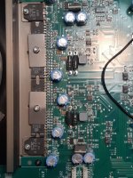
Here is the board of the Majik... wow those trimmers are small! It makes exactly 34W at clipping versus 33W like the spec says. It was sitting for years, I originally planned to somehow make it fully operational, but it was beyond any reasonable repair.
Listening is interesting, I have to get used to it a bit. It definitely sounds different from my tube amps, or my usual transistor amps. It makes me very interested to hear what a composite design can do!
Listening is interesting, I have to get used to it a bit. It definitely sounds different from my tube amps, or my usual transistor amps. It makes me very interested to hear what a composite design can do!
Attachments
Here is the board of the Majik... wow those trimmers are small! It makes exactly 34W at clipping versus 33W like the spec says. It was sitting for years, I originally planned to somehow make it fully operational, but it was beyond any reasonable repair.
Listening is interesting, I have to get used to it a bit. It definitely sounds different from my tube amps, or my usual transistor amps. It makes me very interested to hear what a composite design can do!
Tube amps will almost always be different. Gentle and pleasant sound but no need to look at measurement results. Ideal for classical, jazz and folk music. Not at all suited for punchy bass. The sound of your usual transistor amps depend on the age. If of the elder type, modern chip-amps may be more transparent and with a more firm bass than your usual transistor amps. The TDA1514 was the best class AB chip from Philips/NXP and their chip designers were skilled.
For the composite amplifiers, it is mainly the OP-AMP that decides the sound. Expect even more transparency and precision in the sound, not tube sound.
I think it is unfair to write off tubes like that, a big powerful tube amp with big sensitive speakers will do rock music, or orchestral music justice. A lot of tube amps in use suffer from bad design and low power though. That said, I'm somehow much less worried about a TDA1514 catching fire, it will never degrade over time. And what is life without trying new things? I've been listening to these paralleled ICs all afternoon and they seem to sound better and better.
Solid state amps have been many, mostly vintage stuff though. I repair equipment, and have had the opportunity to test a lot of it. I usually wrote off chip amps due to my distaste for Sanyo STK based amplifiers, but building an op-amp based preamplifier stimulated my interest.
You are absolutely the reference on tube sound compared to me. I only have a very limited knowledge on tube-amps from my childhood where solid state technology had entered the electronic scene some years before I started. I still have a box in the basement with tubes I removed from radios and TVs at that time. When it comes to practicality and power efficiency (Greta
 ), the solid state technology scores high.
@Chris
Digikey did not sell you fake chips!
The data sheet claims 20W/4Ohm and 30W/8Ohm.
If you look at your spread sheet and use R=U/I you will see that the numbers you measured are perfectly in line with Ohms Law. It does not even matter if 1, 2 or n chips work in parallel, the Ohm, Volt, Ampere ratio will stay constant.
The claimed 4 A are an absolute maximum value that the chips can stand for a short while, depending on the heat sinking. If you want to see such high current, you have to go under the recommended load impedance of 4 Ohms, maybe 2.9 Ohms. But please, do not try without a proper heat sink.
The 4A get relevant, if you bridge two chips. Such an amp, with 4 Ohms load you will get near them.
Good morning Chris,
A sound principle in testing an electronic item is to vary only one parameter at the time and keep all the other parameters fixed at values within specified operational limits meanwhile. As Turbowatch2 says, it is very unlikely that you got fake chips from Digikey. Worst case, some of the chips you have may have suffered damage from hard treatment - we will see.
So, a supply voltage of +/-20-25V. A good heatsink! No load for a start. 1KHz sine-wave. The chip should be able to clip at some 3V below the supply voltage. Until clipping, the sine-wave should look fine. At clipping, the flat tops should be rather clean without oscillation. If this test is passed well you continue.
Then, same setup but this time with a load of 8-10 Ohm. 8-10 Ohm with 25V supply will not reach the 4A limit of the LM1875 and not even the test limit of 3A due to the voltage drop in the output stage (2-5V depending on the current). So, clipping should happen near 4V below the supply voltage and the sine-wave look fine until then. A bit of "wool" at the flat tops. If still OK, you continue.
Now 4-5 Ohm loading. With 4 Ohm loading, the 3A test limit is reached at 12V peak and the 4A limit at 16V peak. We know up front that there will be problems at high amplitude. You increase the amplitude until it starts looking strange which should be from 15-16V peak. When the limit is reached you note the limit and lower the amplitude not to stress the chip from increased heating. Current limitation is activated so you cannot rely on nice flat tops.
If you successfully passed these tests, the IC is fine. Only the short-circuiting tests will decide if it is fake but I would be careful with those and only perform such with reduced supply voltage and for short moments.
The big mess starts when you use a load that you have used before but which will cause current limitation, you let the chip heat up significantly so you are not sure how it behaves, the unregulated supply voltage sags and it all looks weird for which reason you declare the chip "fake". You simply lost overview.
Ruhig - ruhig - ruhig.
After having concluded that the chip is OK, you can try with square-waves, increased frequency, changing the supply voltage etc. BUT only vary one parameter at the time.
In electronics, the principle apply that it is much easier to make the system work under gentle conditions and then harden the conditions until poor operation (seeking the limits of operation), than starting the system up under conditions where it performs poorly and try to bring it to proper operation.
Last edited:
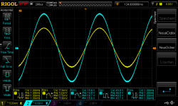
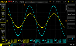
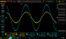
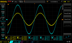
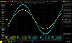
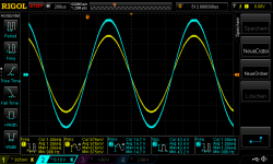
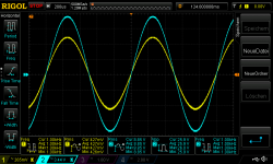
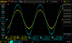
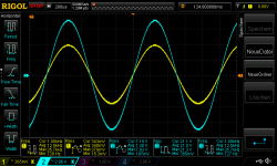
As suggested by Chris in posting #399, 2.7 Ohm in parallel with 100nF or 1uF.
Still my unregulated power supply with +/-24V.
Picture 1: 1KHz, 20Vpp, 2.7 Ohm in parallel with 100nF
Picture 2: 1KHz, clipping, 2.7 Ohm in parallel with 100nF
Picture 3: 1KHz, 20Vpp, 2.7 Ohm in parallel with 1uF
Picture 4: 1KHz, clipping, 2.7 Ohm in parallel with 1uF
In conclusion, the triple LM1875 is pretty unimpressed by capacitive loading.
Attachments


As suggested by Chris in posting #399, 2.7 Ohm in parallel with 100nF or 1uF.
Still my unregulated power supply with +/-24V.
Picture 1: 1KHz, 20Vpp, 2.7 Ohm in parallel with 100nF
Picture 2: 1KHz, clipping, 2.7 Ohm in parallel with 100nF
Picture 3: 1KHz, 20Vpp, 2.7 Ohm in parallel with 1uF
Picture 4: 1KHz, clipping, 2.7 Ohm in parallel with 1uF
In conclusion, the triple LM1875 is pretty unimpressed by capacitive loading.
Can you get any ringing on the square waves if you use, say, 1uF without parallel resistance? A pure capacitive load won't have a resistor to damp ringing and may provoke a square wave which looks a bit less textbook perfect.
With such nice behavior on the scope I bet it already sounds good.
You are absolutely the reference on tube sound compared to me. I only have a very limited knowledge on tube-amps from my childhood where solid state technology had entered the electronic scene some years before I started. I still have a box in the basement with tubes I removed from radios and TVs at that time. When it comes to practicality and power efficiency (Greta
Ahh, some day you should listen to an expensive tube setup like ARC or something and hear what all the fuss is about. Aside from sounding good, they are very interesting to play with, although contrary to the concept of keeping a low hobby profile for your wife's sake!
Anyway, I've been working with tubes for years, so time for a change. I hope we can make these TDA2050 sound close to as good as the TDA1514A does, because after more time I still can't believe I'm hearing a chip amp. All it needs to be perfect is more power! As a vacuum tube enthusiast I am not surprised that Philips made some good ICs, after all they made some of the best tubes ever made as well.
Last edited:
I was asked about the -3dB bandwidth. I tested with two signal amplitudes (2.7 Ohm load / +/- 24V supply):
20Vpp gave 100KHz (slew-rate determined / triangular)
2Vpp gave 180Khz (slew-rate determined / triangular)
I also tested the slew-rate with 2.7 Ohm load and 20Vpp square-wave. I arrived at 3.3V/us. A "raw" LM1875 is specified to 8V/us but I have reduced the speed with the 100pF in the feedback.
20Vpp gave 100KHz (slew-rate determined / triangular)
2Vpp gave 180Khz (slew-rate determined / triangular)
I also tested the slew-rate with 2.7 Ohm load and 20Vpp square-wave. I arrived at 3.3V/us. A "raw" LM1875 is specified to 8V/us but I have reduced the speed with the 100pF in the feedback.
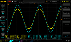
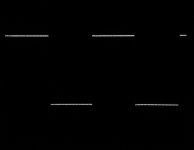
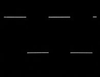
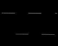
As requested, only 100nF or 1uF but no resistive loading. Actually, it does not change much.
Picture 1: 1KHz, 20Vpp, 100nF (no resistive load)
Picture 2: 1KHz, 20Vpp, 1uF (no resistive load)
NB: foil capacitors.
Picture 1: 1KHz, 20Vpp, 100nF (no resistive load)
Picture 2: 1KHz, 20Vpp, 1uF (no resistive load)
NB: foil capacitors.
Attachments

Last edited:
- Home
- Amplifiers
- Chip Amps
- LM1875 in parallel configuration and used in a composite amplifier.