Hi Chris,
It makes sense to preselect (match) the gain setting resistors such that trimming of them becomes unnecessary. The low resistance (power) load sharing resistors should not be corrected as they are difficult to adjust and trimming would only influence load sharing moderately. Keep the load sharing resistors standard 5% as concluded by Preamp.
oh...yes thats logical...and i understand.
If you change the 100 Ohm into 8 Ohm, the relative difference in LM1875 currents become much less.
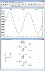
That's not the case, at least with my simulation. Reducing the load to 8R and reducing the input level to 500mV yields about the same result as before. With an input level of 3Vp into 8R, I get almost 1.5Ap load current, split to 0.234/0.333/0.911Ap respectively (without anything clipping). The split ratio remains the same, and one amp does most of the work. When that one runs into clipping, things start to become ugly.
Increasing the load sharing resistors helps in any case. Trade-off is their increased dissipation of course.
This is what things look like if you can select the resistors to within +-1R. Shown are the worst-case combinations of 999R/4001R (one low, one high) and 1001R/3999R (one high, one low) as compared to a perfect 1k/4k for 2Ap into 8R. Doesn't look too bad and should be realistic to achieve in practice. But again it's one more step that needs manual labor and that should not be skimped on.
Attachments
That's not the case, at least with my simulation. Reducing the load to 8R and reducing the input level to 500mV yields about the same result as before. With an input level of 3Vp into 8R, I get almost 1.5Ap load current, split to 0.234/0.333/0.911Ap respectively (without anything clipping). The split ratio remains the same, and one amp does most of the work. When that one runs into clipping, things start to become ugly.
Increasing the load sharing resistors helps in any case. Trade-off is their increased dissipation of course.
Hi Lasse,
Very good work with your simulations. I was an active lab.-engineer before such simulation tools became generally available. It is a good development engineers primary task, as fast as possible, to point to the issues that are least obvious to solve.
I may have been too optimistic when I believed that no trimming would be needed.
Preselection (matching) of resistors in the order of 0.025% I do not believe is practical.
Do you agree with me that it is rather the gain matching that is important and less the static offset?
If we could avoid adjusting static offset, trimming for gain-matching could be possible. I am no believer in trim-potentiometers as they are not long term stable and often not found in the outer ends of the resistor value range anyway. I prefer (high-value) parallel resistors put across the resistors to be adjusted. As I normally arrange the LM1875 feedback resistor on the rear side of the PCB, directly on the LM1875 terminals, and the feedback resistor is larger in value than the input resistor, I prefer adjusting the input resistor value by adding a high value resistor in parallel with the input resistor.
The LM1875 power stages we intend to use are DC coupled such that gain matching can be done statically. With a rather stable DC voltage on the input of the number of LM1875 power stages arranged in parallel, leaving an output voltage in the order of 15Vdc, the LM1875 output with the highest voltage can be identified. Then, a volt-meter is connected to that (highest voltage) output and an output to be adjusted. Trying different high-value resistors in parallel with the input resistor makes it possible to identify and connect the high-value resistor that leaves the least voltage difference to the output with the highest voltage. Then, the same procedure is repeated with the other output to be adjusted (for three LM1875 in parallel). This way I guess we can achieve voltage differences of only a few milli-Volt.
Could that be a useful procedure?
Chris’ suggestion to adapt each output balancing resistor for equal current contribution is in principle good. The problem is to measure the current contribution precisely and as long as there are voltage differences, there will be cross-current issues at low output current levels.
Last edited:
Hi FF
Yes i think your way is practically , logical and not so expensive😉
e.g.
10k - 0,005% - 22 Euro
Y145310K0000V9L Vishay Foil Resistors (Division of Vishay Precision Group) | Resistors | DigiKey
10k - 0,05% - 0,45 euro
MBB02070C1002DC100 Vishay BC Components | Resistors | DigiKey
10k - 1% - 0,03 euro
MRS25000C1002FRP00 Vishay BC Components | Resistors | DigiKey
😉chris
Do you agree with me that it is rather the gain matching that is important and less the static offset?
Yes and no... Up to now I have omitted the input offset in my simulations. After including it now, the results look a little different.
With a rather stable DC voltage on the input of the number of LM1875 power stages arranged in parallel, leaving an output voltage in the order of 15Vdc, the LM1875 output with the highest voltage can be identified. (...) Could that be a useful procedure?
In theory this should work. The simulation result for my worst-case scenario with 0.1% resistors yields a maximum difference of 26mV for 20V output. Unfortunately you also get a difference of 20mV when one amp has a voltage input offset of 2mV and the other one has -2mV. With just measuring the output differentials you could not discern between what is due to input offset and what is gain mismatch. Which makes this a theoretical attempt only and seems to be of no practical value.
That would be another reason not to skimp on gain resistor matching in the first place, so that the gain mismatch is no problem anymore. Now, how would we tackle the offset problem then? On a second thought, the input offset is probably not a constant value that is specific to each device, but varies with temperature and whatnot. That would leave us with basically two options: 1) hand pick the LM's with the lowest offset, use them and live with whatever performance that brings. This would require another test rig and obviously a bunch of devices to pick from. Doable, but you can't just simply buy 3 parts only for one channel and be happy with it. 2) Use a DC servo for each amp. Which brings us back to the start, with a much more complicated design overall.
Just some thougts. Anything obvious that I have missed?
Hi preamp
as far as I can follow you nothing is missed. I build several genuine LM1875 mono amps with this ebay kit and as far as i measured the DC offset is always close to -2mV at every amp.
sorry for that nooby thinking:
Does it make sense to think about a kind of limiter/clipping indicator?? i mean if 3 chip should play together then the weak one is the limited factor and maybe it makes sense to set a LED to know this point.
chris
Ideally we want all 3 amps to deliver equal amounts of power and thus clip at the same time. When one amp clips considerately earlier than the others, you might as well just use that one alone.
Your offset observations sound promising, but we can't take that as a given. What can be done if the offset doesn't look that good? Trim it away or buy new parts? What to do with the unused parts then?
Your offset observations sound promising, but we can't take that as a given. What can be done if the offset doesn't look that good? Trim it away or buy new parts? What to do with the unused parts then?
Hi
i did a measurement at my ebay kit with bests parts and I look at the DC offset to go ahead with my double amp - paralleling 2 chips. i soldered a 0R1 5W resistor . i observed -2mV/-1,9mV with my lab power supply at +/-27V. with +/- 25V i get a little bit less -1,8mV/-1,7mV.
then i did a test to look again the gain setting of both amps. i forget to DMM at the output and start with a sweep of 10Hz to 35khz and see that the DC offset is going up/down. this forced me to look closer:
+/-27V power supply - amp 1
400mVrms input with 1khz - 29,2mV Dc offset - 9,04Vrms at 8R
500mVrms input with 1khz -15mV Dc offset - 11,1Vrms at 8R - 15Watt
500mVrms input with 8khz - 53,3mV Dc offset - 11,1Vrms at 8R
500mVrms input with 10khz- 42,7mV Dc offset - 11,1Vrms at 8R
then i search for the highest DC offset - its at 12khz
650mVrms input with 12khz- 57,9mV Dc offset - 14,2Vrms at 8R - 25Watt
730mVrms input with 12khz- 62,2mV Dc offset - 15,6Vrms at 8R - 30 Watt
the second amp was not able - chip by digikey - to handle +/-27V with 400mVrms input - i got again this switch on/off mode!
+/-25V power supply - amp 1 + amp 2 without problems
400mVrms input with 1khz- 28,8/28,6 Dc offset - 8,88 /8,86Vrms at 8R
500mVrms input with 1khz -14,7/14,6mV Dc offset - 11,0Vrms at 8R - 15Watt
500mVrms input with 8khz - 53/52,9mV Dc offset - 11,1Vrms at 8R
500mVrms input with 10khz- 43,7/43,5mV Dc offset - 11,1Vrms at 8R
658mVrms input with 10khz- 55,2/56,8mV Dc offset - 12,9/12,7Vrms at 8R - 20Watt
650mVrms input with 12khz- 59,2/60,8mV Dc offset - 14,1/13,9Vrms at 8R - 25Watt
670mVrms input with 12khz- 61,7/63,5mV Dc offset - 14,4/14,4Vrms at 8R - 27Watt
chris
Was your generator AC coupled? Can you measure the DC part of your generator alone, the same way that you did with the amp (with a multimeter)?
Hi Preamp
my generator is the DG1022 and i do not set the offset - offset is 0,00V at any time. my DMM is a Voltcraft VC280 and the the setting was at mV.
so your suggestion is that my generator produce this DC offset?
chris
my generator is the DG1022 and i do not set the offset - offset is 0,00V at any time. my DMM is a Voltcraft VC280 and the the setting was at mV.
so your suggestion is that my generator produce this DC offset?
chris
Yes, that is what I wanted to know. Might be possible, and even a small amount would be amplified. You could add a decoupling cap between generator and amp and check again
Yes, that is what I wanted to know. Might be possible, and even a small amount would be amplified. You could add a decoupling cap between generator and amp and check again
Hi preamp
you are right

the internal amp from the generator but some DC offset at the output. i looked at some signals on my scope and switched between DC and AC coupling and see a small jump. according to that i have to say that about 30mV at 400mVrms output will be added. at 700mvrms output it is about 38mV dc.
so this values should be subtract from the values above --- thanks🙂
i looked at my other 2 amps on the right side of my planned amp and they have nearly the same values and both can handle the +/-27V without problems
typo in post #170
658mVrms input with 10khz- 55,2/56,8mV Dc offset - 12,9/12,7Vrms at 8R - 20Watt
580mVrms input with 10khz- 55,2/56,8mV Dc offset - 12,9/12,7Vrms at 8R - 20Watt
Last edited:
Shouldn't your 30mV be amplified by the gain factor of the amp? 30mV seems excessive if you multiply it by 10 or even 20...
Just put a 10uf electrolytic (or whatever you have handy) at the amp's input (or generator's output FWIW) and repeat the test. That should get rid of any DC at the input, however large it may be.
Just put a 10uf electrolytic (or whatever you have handy) at the amp's input (or generator's output FWIW) and repeat the test. That should get rid of any DC at the input, however large it may be.
.....................................................
That would be another reason not to skimp on gain resistor matching in the first place, so that the gain mismatch is no problem anymore. Now, how would we tackle the offset problem then? On a second thought, the input offset is probably not a constant value that is specific to each device, but varies with temperature and whatnot. That would leave us with basically two options: 1) hand pick the LM's with the lowest offset, use them and live with whatever performance that brings. This would require another test rig and obviously a bunch of devices to pick from. Doable, but you can't just simply buy 3 parts only for one channel and be happy with it. 2) Use a DC servo for each amp. Which brings us back to the start, with a much more complicated design overall.
..................................................................
Hi Lasse,
You really know how to nail my less solid solutions. You are needed in politics.
You are right! If we install two, three, four or even six LM1875 and then realize that some have more than the typical input offset, what do we then do? Change those LM1875 and hope that the ones we put in as replacement are better? Or, screen all the LM1875 before mounting?
True, we need to advise a practical solution.
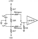
A solution involving trimming of input offset is technically not very complex. Please see the schematics appended. A slight positive voltage and a slight negative voltage are created such that these voltages can be used with voltage dividers to compensate the input offset using the non-inverting input of the LM1875.
The relevant one of Rtrimpos and Rtrimneg is chosen such that the input offset (up to 15mV) is compensated.
Chris has done valuable work showing that in many cases the input offset is so low that no trimming is needed. What we should provide is means to trim the offset voltage but ONLY IF needed.
With trimming of both input offset and gain, the procedure becomes:
1) Connect all inputs of LM1875 power stages to ground.
2) If an LM1875 output exceeds 2mV, choose either Rtrimpos or Rtrimneg such that the output voltage becomes less than 1mV. Install that resistor value.
3) Connect all inputs of LM1875 power stages to 4.5Vdc relative to signal ground.
4) Identify the LM1875 output with the highest voltage. Connect one voltmeter test-wire to that output. Connect the other voltmeter test-wire in turn to all other outputs with a positive voltage.
5) If the voltage of an output deviates from the voltage at the output having the highest voltage with more than 5mV, find a resistor which in parallel with the input resistor reduces the voltage difference to less than 5mV. Install that resistor in parallel with the input resistor.
6) Identify the output with the most negative voltage. Connect one voltmeter test-wire to that output. Connect the other voltmeter test wire in turn to all other outputs with a negative voltage.
7) If the voltage of an output deviates from the voltage at the output having the most negative voltage with more than 5mV, find a resistor which in parallel with the input resistor reduces the voltage difference to less than 5mV. Install that resistor in parallel with the input resistor.
What-about-such-a-solution?
Attachments
The 5534 clips nicely.
Should we reconsider?
My idea was to use a DIL-8 socket such that NE5532, OPA2134, LM4562 (LME49720) and OPA1612 (with converter) can be used at choice. Should someone make a PCB layout sometime, the OPA1612 could be a good choice.
Ideally we want all 3 amps to deliver equal amounts of power and thus clip at the same time. When one amp clips considerately earlier than the others, you might as well just use that one alone.
Your offset observations sound promising, but we can't take that as a given. What can be done if the offset doesn't look that good? Trim it away or buy new parts? What to do with the unused parts then?
Hi Lasse and Chris,
Your clipping (saturation) concern I cannot follow. If we use LM1875 from the same production batch, I expect that they will clip (saturate) at very similar levels. Evidently, one will saturate (clip) before the other. At that moment the one saturating will no longer provide a variable current but a fixed current while the other will still increase their current until they also clip. Clipping is a moment where there inherently will be distortion so consideration of delicate load balancing at that moment seems exaggerated to me, as long as no LM1875 gets overloaded.
Should there be a situation at clipping where one LM1875 suddenly takes most of the load current, we may consider limiting the amplitude at the LM1875 inputs such that none of the LM1875 saturate.
Last edited:
I have to vote for the idea where none of the 1875 clips.
The opamp will try to compensate that and the result will look quite horrifying.
Also, every opamp needs different compensation. Switching opamps on the run, is not possible.
But, there probably has to be a preamp for the BTL-circuit to drive both halves? That preamp should be changeable (on a socket).
I have to vote for the idea where none of the 1875 clips.
The opamp will try to compensate that and the result will look quite horrifying.
Also, every opamp needs different compensation. Switching opamps on the run, is not possible.
But, there probably has to be a preamp for the BTL-circuit to drive both halves? That preamp should be changeable (on a socket).
A good year ago, I made a composite amplifier with only one LM1875 at the output. At clipping of the LM1875, the OP-AMP (which was not saturated) tried to compensate the non-linearity in a logical way but nothing looked horrifying. The LM1875 output clipped the usual way and the OP-AMP output showed some distortion where the LM1875 was saturated but it did not latch-up or anything serious. When the LM1875 came back to unsaturated (active), the OP-AMP output returned to sine-wave shape.
With the same compensation of the OP-AMP, I could use NE5532 and OPA2134 interchangeably. I did not try with LM4562.
For BTL, my hope is that a first controlling OP-AMP can serve to control half of the LM1875 power stages while a second OP-AMP can control the other half of the LM1875 power stages and turn the phase 180 degrees at the same time. I haven't thought of it in detail yet.
NB: I read that Finland is going to try a four day working week, which I find courageous and encouraging. But, I notice you are active at 5:36 in the morning. Is that a less known consequence? 😀
- Home
- Amplifiers
- Chip Amps
- LM1875 in parallel configuration and used in a composite amplifier.