Good morning gentlemen
i want to remind you that I am not so fast 😛😉 #post 1
https://www.diyaudio.com/forums/chi...guration-composite-amplifier.html#post6007512
this are the first points we should discussed. and lets do it step by step please
a) Discussion of principles and design details, initially of a parallel LM1875 amplifier.
b) Establishment of a design for a parallel LM1875 amplifier.
c) Construction and test of such a parallel LM1875 amplifier.
d) Design of an OP-AMP control loop for the parallel LM1875 amplifier in a composite amplifier configuration.
composite:
FF did a successful test with his construction and it works:
composite amplifiers
chris
Last edited:
chermann , please look at post 38. The discussion I proposed for voltage/ current mode of paralleling, FF didn't reply . I suppose he doesn't like My Ref style . To parallel low impedance voltage outputs you need series resistors , he chose 0.33 to 0.5 ohms. Now we are fixed with the power stage topology. What gain ,Fr ,should the 1875 's must have ? There are two options . Eider the outputs have high gain with low frequency response to bear the dominant pole, and the op amp is low gain and high frequencies response, or the opposite. In the first case the op amp doesn't contribute to any enhancement but for offset, the opposite is the one to follow as I did fixing the gain to minimum stable of 2.8. once you test the sound then to apply a pair of it bridged with an input split transformer. After measurements , to apply several pairs bridged to see how the offset of paralleled amps are reacting with each other . Apply then the composite op amp and determine how to pass single input to differential.
This needs a prototype.
But if it works, its pretty much super.
And if it dont, what does it need to make it work?
Looks good as well.
One detail puzzles me - the gain in the LM1875 stage. Inverting coupling with a gain of 2K/1K=2. I would love to make a parallel LM1875 power stage with a gain of 2-4 knowing that it would be feed from an OP-AMP with good supply rails. But, I feel limited by statements in the LM1875 datasheet: "The amplifier is internally compensated and stable for gains of 10 or greater" (last sentence of the Description on page 1); "The LM1875 is designed to be stable when operated at a closed-loop gain of 10 or greater......" (chapter Stability on page 7).
My question: Do you know from experience or information outside of the datasheet that LM1875 can be used with a good stability margin when having a closed loop gain of 2? I will be happy if it is possible. Stability will be essential in a composite amplifier loop.
Last edited:
I know from experience, that in inverting mode the 1875 is stable even at negative gains.
But I have never prototyped it in a composite configuration.
So, it must be prototyped, otherwice we can not know for sure.
Unfortunately, I have something else on my testbench right now, so I can not quickly proto this just at the moment.
🙂
As most of the THD is noise, minimizing that is essential.
Inverting the 1875 reduces noise a lot.
One step at a time is OK by me, though...
Edit:
I can see Stanislav has the same concept as me, at the other thread...
Last edited:
chermann , please look at post 38. The discussion I proposed for voltage/ current mode of paralleling, FF didn't reply . I suppose he doesn't like My Ref style . To parallel low impedance voltage outputs you need series resistors , he chose 0.33 to 0.5 ohms. Now we are fixed with the power stage topology. What gain ,Fr ,should the 1875 's must have ? There are two options . Eider the outputs have high gain with low frequency response to bear the dominant pole, and the op amp is low gain and high frequencies response, or the opposite. In the first case the op amp doesn't contribute to any enhancement but for offset, the opposite is the one to follow as I did fixing the gain to minimum stable of 2.8. once you test the sound then to apply a pair of it bridged with an input split transformer. After measurements , to apply several pairs bridged to see how the offset of paralleled amps are reacting with each other . Apply then the composite op amp and determine how to pass single input to differential.
The reason for my possibly limited reply is that I do not know the topologies "voltage or current Holloway?". The very traditional solution I propose is balancing consumption from parallel voltage sources by transforming them in part into current sources with the resistors. Is that voltage or current Holloway? From a later posting of yours it appears to be voltage Holloway. We have not fixed anything yet. I am trying to explain to less experienced members what we are discussing and at the same time I add a personal opinion to give them some practical guidance for understanding. Experienced members like you can add suggestions, corrections and arguments and only at the end of the discussion we fix principles and component values as guide for those who actively take part.
I know from experience, that in inverting mode the 1875 is stable even at negative gains.
But I have never prototyped it in a composite configuration.
So, it must be prototyped, otherwice we can not know for sure.
Unfortunately, I have something else on my testbench right now, so I can not quickly proto this just at the moment.
🙂
As most of the THD is noise, minimizing that is essential.
Inverting the 1875 reduces noise a lot.
One step at a time is OK by me, though...
Edit:
I can see Stanislav has the same concept as me, at the other thread...
Many thanks for your reply. Very interesting experience that is outside of the datasheet telling. Until now I just followed the datasheet information blindly. If it is stable, it should work in a composite amplifier as well. As we are not in a hurry (I guess) and Christmas/New Year will soon require our attention on other matter as well, it would be nice to investigate stability of the LM1875 with low closed loop gain a little before deciding on a particular design.
An explanation for less experienced members.
A goal with this small project is to construct a composite amplifier. A composite amplifier is substantially a double-loop regulated system. It is a nested regulation system in the sense that one regulation loop is put inside the other regulation loop. This is a structure many of us know better from modern cars so I will explain for a start with reference to a car.
A modern combustion engine is controlled by an engine control system that controls supply of petrol, air, valve positions etc. to ensure a reliable and efficient functioning at different rotation speeds. That is a first (inner) regulation loop. Outside of that regulation loop, you have a regulation system that ensures that when you push the gas pedal you have a smooth acceleration and when you release the gas pedal, the engine reduces power such that you have a smooth engine breaking effect. If the engine control system does not work well, such that the engine instead reacts in an unpredictable and unintended way, this second gas pedal loop is of little or no use. Today you even have a third outer loop when you engage the cruise control to keep a constant speed. It uses the gas pedal system electronically to give more or less gas such that the right speed is kept. But again, if the engine control system does not work well such that the engine actually performs irregular, the cruise control can’t help much. Similarly, if the gas pedal regulation system does not function well such that the engine suddenly gives a lot of power and acceleration, or suddenly cut almost all power from the engine, the cruise control will not work well. For such a mechanical/electronic system you will have to solve problems starting with the innermost regulation system and then work your way out. It is similar for audio amplifier regulation – the better you solve problems in inner loops, the easier it is to make outer loops work.
The inner system in a composite amplifier is the power amplifier (that may in detail be made up of more amplifier blocks) which is a regulated electronic system. We can see it as a single loop regulated system though it in reality may include a plurality of regulation loops. Similar to the engine control system described above – only if the power amplifier works well you can go on with an outer regulation loop. “Works well” entails that it is reliable (no sudden misbehavior such as self-oscillation), predictable (absolutely unambiguous response at the output to a given input signal) and preferably linear (such that the output is reasonably proportional to the input). This is why you may see more effort put into construction of the power amplifier than just achieving load sharing can explain. Stability of the power amplifier is crucial because important misbehavior of the power amplifier (such as self-oscillation or heavy distortion) is something an outer loop can do very little about or may even make worse.
The outer OP-AMP control loop in a composite amplifier serves to correct fine or more moderate distortion in the power amplifier, it cannot correct major deficiencies in the power amplifier performance. When the power amplifier is constructed well, the typically superior performance of the OP-AMP will characterize the whole composite amplifier performance. Therefore, the very low THD if designed well.
A detail is that many class AB amplifier chips are stated only to be stable for gain of 10 (20dB) and above. It is possible to make composite amplifiers with gain of more than 10 times in the chip amp but it can be inconvenient. High gain in the chip amp means high amplification of the more mediocre noise performance of a chip amp. High gain in the chip amp means low signal level at the output of the controlling OP-AMP. The OP-AMP can do that but it may operate in an amplitude range with less good THD performance. If the gain in the chip amp could be reduced below 10 times, it would benefit noise and allow the OP-AMP to operate at lower THD levels.
To my personal surprise, two experienced members just told that the LM1875 can operate with a closed loop gain well below 10 times. It is absolutely worth taking into account.
Last edited:
I have managed to get a TDA2030A running stable in a non-inverting configuration with a gain of 2. The frequency response is something to watch out for, but THD and noise performance increase substantially. I don't know how similar the TDA2030A and the LM1875 actually are, but since the 1875' datasheet states the same 1R/220n Zobel, I think they might be not too different. Maybe I should order some 1875 and toss one into my prototype while it's still on the bench...?
Here's the thread with the experiences I made along the way: Fun with a cheap TDA2030A at only 6dB gain
Note that I had some trouble with an inductive resistor in the Zobel network. It is a crucial part for maintaining stability.
Here's the thread with the experiences I made along the way: Fun with a cheap TDA2030A at only 6dB gain
Note that I had some trouble with an inductive resistor in the Zobel network. It is a crucial part for maintaining stability.
..........schematics.
Many thanks for the link. Many good schematics showing parallel couplings and BTL configuration. Will serve as inspiration.
FF i will never say/write that you made a mistake....😉
if i did no mistake at my workbench....😀
original TI chip...to confirm this test i will do this test with my amp boards = amp 1_2 the nichicon UES board....
Hi
the board in psot 24 has the chip code printed 73JT - and for correction i bought this at digikey.
the other 2 amp boards show similar. i get oscilation but in the other thread we discussed this.
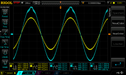
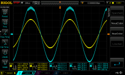
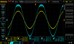
pic 1 72BD chip_20V supply 460mVrms in at 4,459R_no clipping
pic 2 72BD chip_18V supply 410mVrms in at 4,459R_no clipping
pic 3 84AH chip_20V supply 460mVrms in at 4,459R_no clipping
pic 4 84AH chip_18V supply 410mVrms in at 4,459R_no clipping
DC offset connected with my freq. generator but no signal - no load:
amp with 72BD
+/-20V supply -2,3mV
+/-25V supply -2,7mV
+/-27V supply -2,9mV
amp with 84AH
+/-20V supply -2,7mV
+/-25V supply -3,1mV
+/-27V supply -3,4mV
chris
Attachments
-
 72BD chip_20V supply 460mVrms in at 4,459R_no clipping_new caps.png52.4 KB · Views: 559
 -
 72BD chip_18V supply 410mVrms in at 4,459R_no clipping_new caps.png52.6 KB · Views: 578
 -
 84AH chip_20V supply 460mVrms in at 4,459R_no clipping_new caps.png52.8 KB · Views: 564
 -
 84AH chip_18V supply 410mVrms in at 4,459R_no clipping_new caps.png53 KB · Views: 566
I have managed to get a TDA2030A running stable in a non-inverting configuration with a gain of 2. The frequency response is something to watch out for, but THD and noise performance increase substantially. I don't know how similar the TDA2030A and the LM1875 actually are, but since the 1875' datasheet states the same 1R/220n Zobel, I think they might be not too different. Maybe I should order some 1875 and toss one into my prototype while it's still on the bench...?
Here's the thread with the experiences I made along the way: Fun with a cheap TDA2030A at only 6dB gain
Note that I had some trouble with an inductive resistor in the Zobel network. It is a crucial part for maintaining stability.
Hi Lasse,
Many thanks for the link to your thread. I noticed your thread a couple of weeks ago but already at that time there were so many intelligent postings that I felt somewhat intimidated. Anyway, why use a chip amp at 6dB gain? Now I know.
The trick with the resistor between the two input pins I was aware of but also the poor offset voltage result. Going through the postings I noticed PRRs intelligent proposal to increase gain only at higher frequencies and have 26dB gain at the second pole frequency. This is for TDA2030 but I would guess there is a similarity with the LM1875 design so we may use the same trick. Thanks for letting us know. I have 1 Ohm/2W metal film resistors for the Zobel network.
Your location is "Monkey Island". There are probably about as many monkeys in Germany as in other north European countries so that is no identifier. However, Germany has very few islands. "Monkey Island" should be in Brunswick.
Last edited:
Hi Chris,
Kokoriantz and palstanturhin kindly made us aware that LM1875 can operate with gain significantly below 10 times (20dB). Preamp referred to a thread in which PRR suggests a trick to keep a chip amp stable at low gain in the audio band. That can be very convenient for our design.
I hope I can find time here around Chrismas to make simple mock-up and test it out. I will also see what I can do about the self-oscillation on the tops of the sine-wave. I never got around to do much experimenting on that problem because my previous LM1875 board was so compact that I could hardly make changes.
Hi Chris,
Kokoriantz and palstanturhin kindly made us aware that LM1875 can operate with gain significantly below 10 times (20dB). Preamp referred to a thread in which PRR suggests a trick to keep a chip amp stable at low gain in the audio band. That can be very convenient for our design.
I hope I can find time here around Chrismas to make simple mock-up and test it out. I will also see what I can do about the self-oscillation on the tops of the sine-wave. I never got around to do much experimenting on that problem because my previous LM1875 board was so compact that I could hardly make changes.
Hi FF
yes good ideas by the "new" experts here...i read that thread with 6db weeks agao -but i can´t remember what ....😛😛😛
yes over the holidays we can do something - first relax and then the project.😉
about the oscillation:
as you can see at my first pic i use a test board never hear and i got no oscillation - rabbitz is using very small decoupling caps at the board.
nevertheless you guide me how to do it:
100pf parallel at the NFB resistor
check the zobel network -resistor could be inductive (like in the "6db thread")
and the 0,5W resoistors are less noise - especially at the NFB
5k or more at the pin 1-2
have a nice day/night
chris
Last edited:
....I couldn't find out why the rms and not the peak. ...
Maybe review the basic meaning of "RMS"?
> design a transformer
Transformers have lower ampacity because the heat can't get out. As someone here says, the fusing current is much much higher. The ampacity for safe temperatures for a few (five?) wires in open air is somewhere in between.
Going through the postings I noticed PRRs intelligent proposal to increase gain only at higher frequencies and have 26dB gain at the second pole frequency. This is for TDA2030 but I would guess there is a similarity with the LM1875 design so we may use the same trick.
This should work with any op amp out there. I did a quick test with one half of an LM1876 - it works, but is only marginally stable. Unfortunately the standard configuration with 27dB gain isn't 100% stable, too. It shows some mV of ++MHz noise, which is not there with the TDA2030A. Probably due to bad wiring and insufficient supply decoupling; I'll try to figure that out.
Ordered some LM1875 to see how they compare to the TDA2030A.
Your location is "Monkey Island". There are probably about as many monkeys in Germany as in other north European countries so that is no identifier. However, Germany has very few islands. "Monkey Island" should be in Brunswick.
I'm a huge fan of the Monkey Island games from Lucas Arts and like to compare Booty, Phatt and Scabb Island with Sylt, Föhr and Amrum. Call me a monkey if you like; I like bananas 😀. Now you have only three islands left to choose from, which is probably a lot less than "The mountains" that you live in 😉
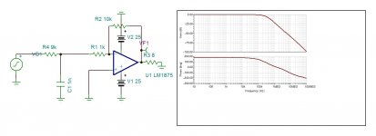
This circuit can lower the gain with flat response, whereas done for tda2030 or PPR proposition gets increasing gain with frequency. But for both cases it goes contrary to the purpose of having low gain which is to push the pole to highest possible so that the composit op amp with its dominant pole can impose highest NFB possible.
Attachments
Last edited:
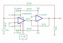
This is a second option . Here the LM1875 is the one that carries the dominant pole at about 20Khz with a gain of 66 db 2000 and the op amp provides a gain of 20db extra . This adds just one zero to the distortion number of LM1875 but the transient response is near perfection.
For my standard ,aged, homo sapiens sapiens specie ears which cannot hear distortions down to 0.1%, this amp should sound excellent. For those of "Tartarin" specie , who pretend to distinguish distortions bellow 0.1% , the first option should satisfy better their sensitive ears.
For my standard ,aged, homo sapiens sapiens specie ears which cannot hear distortions down to 0.1%, this amp should sound excellent. For those of "Tartarin" specie , who pretend to distinguish distortions bellow 0.1% , the first option should satisfy better their sensitive ears.
Attachments

- Home
- Amplifiers
- Chip Amps
- LM1875 in parallel configuration and used in a composite amplifier.