Hi FF
Yes i will do this. my Accuphase P300V is not working since 2017 - i had this amp 28 years - i did a restoration but it failed--> this is the reason i start to diy...to be honest
but first i want to give this amp a appropriate cap bank. today i listened once again to this "best parts" amp...very very nice. i do not think that its perfect but the sound in the mid and upper frequency level is outstanding...maybe i am biased but ....i do my exercise as usual.
the only thing i saw is that at 510mVrms input - about 12Vrms output at 8R = about 18Watt - i get once again this "ringing" at the top???
chris
Many thanks, Chris.
I believe that what we normally call “ringing” is a damped resonance that is triggered by a fast changing signal. Like when you put a square-wave signal on your amplifier or when you look at the chip output pins in class D. The ringing is normally caused by parasitic inductance and capacitance. “Ringing” will die out with time due to losses.
What you observe at the top of the sine-wave is rather self-oscillation which will not die out with time. One of the really big brains wrote somewhere that an inherent problem with class B is that the currents in the driver and power stage change importantly depending on the deviation of the output from the mid-position (rest position) such that loop-gains change and risk creating instability at certain momentary output levels. In class A the currents change much less. I have observed this self-oscillation with “fake” LM1875s. You have earlier seen it with another “fake” and now with a genuine. You found a way with a resistor between the two input pins but it had some drawbacks as well. Another way of influencing the currents in the driver and output stage is by reducing loading. That can be done by reducing the supply voltage or by running more LM1875 in parallel such that they share the load current.
Self-oscillation can best be investigated empirically. You can try to change the gain or limit the bandwidth with a feedback capacitor in parallel with the feedback resistor (like you did with the 100pF). Self-oscillation is not straight forward to fight and I guess most simulation models are not sufficiently precise to include such second order parasitic effects.
If we could have a statement from the forum-wide highly respected Mr. chermann that the SQ of DIY constructions can reach or even surpass the SQ of much commercial gear, that would be an important incentive for new DIY’ers. We do not do DIY activities just to kill time but because we can, through intelligent work, achieve outstanding results.

Last edited:
Good Morning FF
Thanks you for explanation and kind words.
yes the parallel LM1875 was one way i want to try --> that´s the reason i ask about some parallel boards in the previous posts. or i try with this mono boards but i have actually no idea how to "stack" them or so. in my planned housing there is no room for that and for a "stack" i need a other heat sink...
SQ: i really enjoy listening - its a kind of therapy after hard work in the office/job... I will try to borrow maybe another commercial amp...will see
chris
Thanks you for explanation and kind words.
yes the parallel LM1875 was one way i want to try --> that´s the reason i ask about some parallel boards in the previous posts.
or i try with this mono boards but i have actually no idea how to "stack" them or so. in my planned housing there is no room for that and for a "stack" i need a other heat sink...SQ: i really enjoy listening - its a kind of therapy after hard work in the office/job... I will try to borrow maybe another commercial amp...will see
chris
...first compare with a commercial amp...
Hi
to find how good this best amp parts - BAP - is i compare with my amps i have/organized
i have an old AVR from 2009 Pioneer VSX 919AH- (i got this for 50 euros 2 years ago) it is from 2009 the sound is not so bad. I see just super big power chip amps - no idea what monsters here inside.... the heat sink is very thin and small so the fan is working short but loud...that is really annoying.
tonality is really good, clear a little bit like glass but ok, vocals and instruments real- sound stage "strange"- the amp loose a bit the focus of the vocals and instruments = less focus , foggy = i miss here more darkness, bass steps in the background to give the rhythm is not really possible to follow -
power ok - bad fan
technical found this datas:
Front, Center, Surround, Surround hinten - 140 W pro Kanal (1 kHz, 6 Ω, 1 %)
105 W pro Kanal - (20 Hz bis 20 kHz, 8 Ω, 0,09 %) - Klirrfaktor 0,06 % (20 Hz bis 20 kHz, 8 Ω, 5 W/ch)
1:0 for my LM1875 amp (easy job)
chris
Hi
to find how good this best amp parts - BAP - is i compare with my amps i have/organized
i have an old AVR from 2009 Pioneer VSX 919AH- (i got this for 50 euros 2 years ago) it is from 2009 the sound is not so bad. I see just super big power chip amps - no idea what monsters here inside....
the heat sink is very thin and small so the fan is working short but loud...that is really annoying. tonality is really good, clear a little bit like glass but ok, vocals and instruments real- sound stage "strange"- the amp loose a bit the focus of the vocals and instruments = less focus , foggy = i miss here more darkness, bass steps in the background to give the rhythm is not really possible to follow -
power ok - bad fan
technical found this datas:
Front, Center, Surround, Surround hinten - 140 W pro Kanal (1 kHz, 6 Ω, 1 %)
105 W pro Kanal - (20 Hz bis 20 kHz, 8 Ω, 0,09 %) - Klirrfaktor 0,06 % (20 Hz bis 20 kHz, 8 Ω, 5 W/ch)
1:0 for my LM1875 amp
(easy job)chris
Last edited:
first test with AVR ARcam 390..
here is the first test with stereo mode of my AVR reciver in stereo mode. source direct as the previous post- for sure.
technically the AVR390 is a power house! 20 Hz bis 20 kHz, THD <0,02 %80 WATT into 8R - thats enough. its not easy to "separate" a AVR with a stereo amp price wise - the AVR has a lot of extras ..
first impression is a very stable sound character - silent, no spectacular, good sound, lot of power!, it is very neutral, so no "preferred" area,
sometime it sounds good but not really with sparkling - I miss here a bit rhythm and timing - you know when your legs are moving to the rhythm
I miss the micro details, e.g. the skin of a drum, saxophones "distorded sound" - hopefully you can follow me what i ant to tell you...
its is not soo dark i- the silents in the back stage a bit.
second test will follow.
chris
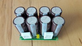
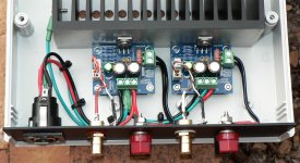
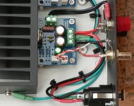
best amp parts - modded psu cap bank
Hi
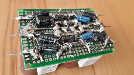
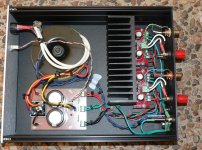
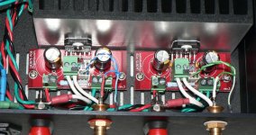
here is the version 2 of my cap bank. the big caps (chemicon 3900µF/35V) and the MPC74 =0,1R are the same but i add under the board some small caps too ...its under test..
chris
Hi
here is the version 2 of my cap bank. the big caps (chemicon 3900µF/35V) and the MPC74 =0,1R are the same but i add under the board some small caps too
...its under test..chris
Attachments

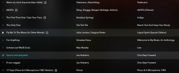
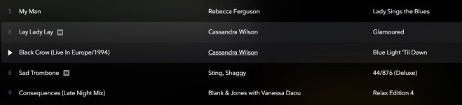
I find it good music for evaluation of audio gear because there are only few instruments and vocals which are quite distinct. But as a musical interpretation, it is about the worst version of Dylan's beautiful "Lay lady lay" I have heard. It completely looses its flow and harmony.
LM3875 minimum
Bear with me here as this is background to my next post about the latest LM1875 build. I want to try a minimum component LM1875 but first I tried a AudioSector LM3875 to see if it was worthwhile.
I was surprised that the amp board was a Chipamp.com PCB and not that usually supplied by PD but shouldn't matter as they are both similar. The power supply PCB was PDs.
Build 1 was a bit "meh" and not what I remember from Peter's kits of years past. I've used a Chipamp.com PCB over a decade ago but can't remember what it was like.
Build 2 tossed out the power supply and made a new one with a bridge rectifier and 2 x 10000uF caps. The balance was all wrong like a BSC circuit with the response running down hill (strong bass and recessed mids and top).
Build 3 kept the new power supply but tossed out the Panasonic FC 1500uF caps near the chip and replaced with 100uF Nichicon KZ and X7R by-pass caps. The sound now came together and is a keeper. I now remember that all the AudioSector kits I built had 100uF caps on the amp PCB and larger caps on the power supply PCB.
The crunch with the minimal approach is horrible DC offset values... 60mV, -90mV with open inputs and 5mV, -11mV with shorted inputs. Depending on the source, the offset can vary such as an active pre gave high offset values and an Ipod gave low offset values.
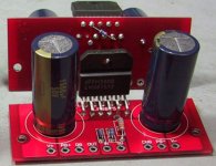
This put me off doing a minimal LM1875 as it really needs the feedback and input caps so did a full Brian Bell LM1875. I've attached pics of the LM3875 just for reference only.
Bear with me here as this is background to my next post about the latest LM1875 build. I want to try a minimum component LM1875 but first I tried a AudioSector LM3875 to see if it was worthwhile.
I was surprised that the amp board was a Chipamp.com PCB and not that usually supplied by PD but shouldn't matter as they are both similar. The power supply PCB was PDs.
Build 1 was a bit "meh" and not what I remember from Peter's kits of years past. I've used a Chipamp.com PCB over a decade ago but can't remember what it was like.
Build 2 tossed out the power supply and made a new one with a bridge rectifier and 2 x 10000uF caps. The balance was all wrong like a BSC circuit with the response running down hill (strong bass and recessed mids and top).
Build 3 kept the new power supply but tossed out the Panasonic FC 1500uF caps near the chip and replaced with 100uF Nichicon KZ and X7R by-pass caps. The sound now came together and is a keeper. I now remember that all the AudioSector kits I built had 100uF caps on the amp PCB and larger caps on the power supply PCB.
The crunch with the minimal approach is horrible DC offset values... 60mV, -90mV with open inputs and 5mV, -11mV with shorted inputs. Depending on the source, the offset can vary such as an active pre gave high offset values and an Ipod gave low offset values.
This put me off doing a minimal LM1875 as it really needs the feedback and input caps so did a full Brian Bell LM1875. I've attached pics of the LM3875 just for reference only.
Attachments
LM1875 using Brian Bell's (Chipamp.com) values
I found Brian Bell's LM1875 component values but no schematic. In brackets [ ] are the components I used in this build.
Reference: Brian Bell (Chipamp.com) LM1875 (schematic unknown)
Default configuration [components used in rabbitz build 2019]
R1 - not used (optional resistor to ground before C1) [not used]
R2 - 22k (input to ground resistor) [0.5W MF]
R3 - 1k (gain resistor , gain = 1 + R4/R [0.5W MF]
R4 - 22k (nfb resistor - on bottom of pcb) [0.5W MF]
R5 - 2.7 2w (optional - zobel network) [2R7 2W MF]
R6 - jumper (optional resistor between input ground and output ground) [not used, linked]
C1 - 2.2µF (optional input capacitor) [1uF MMK]
C2 - 22µF bipolar (optional) [Nichicon ES 22uF 25V]
C3 - 0.1µF (power supply decoupling) [ceramic X7R Vishay BC]
C4 - 47µF (power supply decoupling) [Nichicon KZ 47uF 50V]
C5 - 0.1µF (power supply decoupling) [ceramic X7R Vishay BC]
C6 - 47µF (power supply decoupling) [Nichicon KZ 47uF 50V]
C7 - 0.1µF (optional - zobel network) [MKT]
Note: 1K resistor after input cap not listed above but installed [0.5W MF]
As for a bare minimum configuration, here is what you could run:
R1 not populated
R2 22k (input to ground resistor)
R3 1k (gain resistor, gain = 1 + R4/R3)
R4 22k (nfb resistor - on bottom of pcb)
R5 not populated
R6 jumper
C1 jumper, or put input source into pad by C1 label on pcb
C2 jumper
C3 0.1µF (power supply decoupling)
C4 47µF (power supply decoupling)
C5 0.1µF (power supply decoupling)
C6 47µF (power supply decoupling)
C7 not populated
I like this default version and for my tastes better than the previous build using values with the kit. The presentation was open, smoother, better balanced, less edginess and sibilance, better control. Not a large amount in it but quite noticeable but of course depends on what you like. I will definitely hang onto this version.
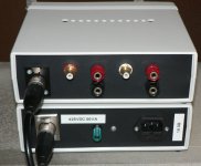
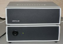
Built in my cheapo Hammond plastic instrument cases and as before the power supply lives in it's own case.
During test over an hour the 0.89°C/W heatsink got to 46°C with ambient at 26°C (yesterday 37°C ambient). DC offset at -1.5mV, -1.8mV which shows the value of the 22uF feedback cap (a must). Power supply was 50VA with 2 x 4700uF caps and supply voltage was ±26.3VDC at idle and not less than ±24VDC under load. Tested with iPod and SB65WBAC + SB12PAC PR (4 ohm nom) speaker and then with SB19ST + 830870 (6 ohm nom) speaker.
The LM1875 had enough power to rattle the SB65WBAC and PR but the other speaker had no issues. I still have to try it in the test system in the next few days.
In short, I'm glad I didn't build the minimal configuration that I was curious about.
I found Brian Bell's LM1875 component values but no schematic. In brackets [ ] are the components I used in this build.
Reference: Brian Bell (Chipamp.com) LM1875 (schematic unknown)
Default configuration [components used in rabbitz build 2019]
R1 - not used (optional resistor to ground before C1) [not used]
R2 - 22k (input to ground resistor) [0.5W MF]
R3 - 1k (gain resistor , gain = 1 + R4/R [0.5W MF]
R4 - 22k (nfb resistor - on bottom of pcb) [0.5W MF]
R5 - 2.7 2w (optional - zobel network) [2R7 2W MF]
R6 - jumper (optional resistor between input ground and output ground) [not used, linked]
C1 - 2.2µF (optional input capacitor) [1uF MMK]
C2 - 22µF bipolar (optional) [Nichicon ES 22uF 25V]
C3 - 0.1µF (power supply decoupling) [ceramic X7R Vishay BC]
C4 - 47µF (power supply decoupling) [Nichicon KZ 47uF 50V]
C5 - 0.1µF (power supply decoupling) [ceramic X7R Vishay BC]
C6 - 47µF (power supply decoupling) [Nichicon KZ 47uF 50V]
C7 - 0.1µF (optional - zobel network) [MKT]
Note: 1K resistor after input cap not listed above but installed [0.5W MF]
As for a bare minimum configuration, here is what you could run:
R1 not populated
R2 22k (input to ground resistor)
R3 1k (gain resistor, gain = 1 + R4/R3)
R4 22k (nfb resistor - on bottom of pcb)
R5 not populated
R6 jumper
C1 jumper, or put input source into pad by C1 label on pcb
C2 jumper
C3 0.1µF (power supply decoupling)
C4 47µF (power supply decoupling)
C5 0.1µF (power supply decoupling)
C6 47µF (power supply decoupling)
C7 not populated
I like this default version and for my tastes better than the previous build using values with the kit. The presentation was open, smoother, better balanced, less edginess and sibilance, better control. Not a large amount in it but quite noticeable but of course depends on what you like. I will definitely hang onto this version.
Built in my cheapo Hammond plastic instrument cases and as before the power supply lives in it's own case.
During test over an hour the 0.89°C/W heatsink got to 46°C with ambient at 26°C (yesterday 37°C ambient). DC offset at -1.5mV, -1.8mV which shows the value of the 22uF feedback cap (a must). Power supply was 50VA with 2 x 4700uF caps and supply voltage was ±26.3VDC at idle and not less than ±24VDC under load. Tested with iPod and SB65WBAC + SB12PAC PR (4 ohm nom) speaker and then with SB19ST + 830870 (6 ohm nom) speaker.
The LM1875 had enough power to rattle the SB65WBAC and PR but the other speaker had no issues. I still have to try it in the test system in the next few days.
In short, I'm glad I didn't build the minimal configuration that I was curious about.
Attachments
I find it good music for evaluation of audio gear because there are only few instruments and vocals which are quite distinct. But as a musical interpretation, it is about the worst version of Dylan's beautiful "Lay lady lay" I have heard. It completely looses its flow and harmony.
Yep..Cover versions are Not always nice.
In this case and thats typical for Cassandra...just Enjoy the Instruments with strange rhythm
Hi RAbbitz
Thanks for this test . a lot of work you did the last days.
i found the low input cap at your board - on my compare amps they were different too:
i had at the green the 10µF nichicon UES and at the other the 4,7µF Wima - now i use this super big 10µF foil. - for me the different in sonic bass is notable and important - so i have to ask you : Are really happy with your 1µF at the input??
chris
Thanks for this test
. a lot of work you did the last days.i found the low input cap at your board - on my compare amps they were different too:
i had at the green the 10µF nichicon UES and at the other the 4,7µF Wima - now i use this super big 10µF foil. - for me the different in sonic bass is notable and important - so i have to ask you : Are really happy with your 1µF at the input??
chris
...other chip amps..
Hi Rabbitz and others
I see at the LM3875 datasheet that this chip is more powerful but the current is still 4Amps max - so its comparable with the LM1875.
the THD and the PSRR is much better.
I know you are experts at chip amps + you (rabbitz) own a Arcam A19.
Can you "confirm" that a powerful chip sounds at lower power /volume level better then e.g. LM1875??
i am asking because in generally i planned to use a other chip in the next future to compare with the LM1875 - but i want to try composite + parallel LM1875 first...so a lot of work
chris
Hi Rabbitz and others
I see at the LM3875 datasheet that this chip is more powerful but the current is still 4Amps max - so its comparable with the LM1875.
the THD and the PSRR is much better.
I know you are experts at chip amps + you (rabbitz) own a Arcam A19.
Can you "confirm" that a powerful chip sounds at lower power /volume level better then e.g. LM1875??
i am asking because in generally i planned to use a other chip in the next future to compare with the LM1875 - but i want to try composite + parallel LM1875 first
...so a lot of work chris


Great Rabbitz, thanks for the feedback.
Why is R4 under the board? Too big?
It's under the PCB in the Chipamp.com kit as it connects the feedback resistor directly to pins 4 > 2 on the LM1875. Builders like to keep this resistor as close as possible to the chip but on the eBay PCB it's close enough so mine is on the top of the PCB.
I've added a link to Brian Bell's LM1875. Finally made a LM1875 amp
I've also added a pic of this resistor under PCB but it's on their LM3875 kit.
Attachments
- Home
- Amplifiers
- Chip Amps
- eBay mono LM1875 kit