It looks like the heat sinks in the Marantz requires you to connect the output devices (or in case of the Modulus-86, the LM3886 ICs) with wires. That's not a good idea.
You should be able to find a regular shaped heat sink (one with a flat side) that you can mount in the chassis instead. That'd be cool.
Tom
You should be able to find a regular shaped heat sink (one with a flat side) that you can mount in the chassis instead. That'd be cool.
Tom
"To get 3db more, I only need to push a little more... And it gets loud"
OK to clarify things here and a little off topic, it is important to understand that the volume control only controls the level of signal incoming to the amplifier stage. The same is done with the accelerator pedal in your automobile.
I do not think this is a good analogy, and someone will get totally incorrect views if extrapolating this analogy into a different context.
A typical preamplifier or amplifier volume control pot (i.e., one which does NOT alter the gain of the amplifier itself, as in the preamplifier designed by Doug Self, found in another thread on DIY Audio), alters the level of the signal coming into the preamplifier or amplifier. The preamplifier or amplifier gain itself is unchanged. So, what in essence is happening is the source signal is being attenuated by the volume pot, and then fed into the gain stage of the preamplifier or amplifier. The preamplifier is ALWAYS amplifying at whatever its specified gain is, and the noise floor is always the same within that gain stage. Thus, it becomes a great balancing act to figure out what gain level (if any) is needed at the previous stage (source or preamp) in order to get good headroom and to maximize signal to noise. If you read Mr. Pass' missives on the Zen amp and preamp, as well as the original Buffer, it becomes clear why it is important to decide whether one wants a buffer or a preamp with gain, as well as to decide what gain level one wants for the amplifier. Benchmark Media has a good discussion of this in a White Paper available o their website, in part to explain why their amplifier design nominally has a lower gain (in order to better interface with higher gain/higher output level sources).
It looks like the heat sinks in the Marantz requires you to connect the output devices (or in case of the Modulus-86, the LM3886 ICs) with wires. That's not a good idea.
You should be able to find a regular shaped heat sink (one with a flat side) that you can mount in the chassis instead. That'd be cool.
Tom
Thanks.. It was just an idea...
I'll keep it simple for my first diy amp 🙂
For casing.. Am I correct to look at 2U cases?
What dimensions (in cm please) are good for 2x mod86 + smps?
I will order 2 mod86 + 2x output inductors in the coming week ( keep two warm for me please)
Then, if I'm correct I will get the BOM to order from mouser..
I I'll start first with populating the boards
Will buy casing, wires, bananas, rca, on/off later (but before Christmas)
I generally recommend the ModuShop 2U x 300 x 430 mm Dissipante chassis. The 2U x 300 x 330 mm Mini Dissipante could be interesting as well. I highly recommend getting the aluminum covers as the steel ones are rather hard on your tools.
Here's the shopping list I generally recommend:
2 x Modulus-86
2 x Output inductor
2 x Binding post (pair)
1 x Power-86
1 x ISS (optional)
1 x Guardian-686 or 2 x Guardian-86 (speaker protection - optional)
1 x Power transformer (2x22 VAC, 160-200 VA for stereo; 200-300 VA for a 4-channel amp).
Chassis, connectors, wire, time. 🙂
If you go with an SMPS you can drop the Power-86 and power transformer. Depending on the features of the SMPS and the features you'd like in your amp, you can decide whether to keep the ISS. The main purpose of the ISS is to provide a soft start for the transformer. It also adds features such as compatibility with momentary switches, such as the many anti-vandal switches (E-Switch PV6-series, for example), and 12 V trigger input.
For the SMPS go with a ±30 V version. I recommend the Connex SMPS300REh.
I consider speaker protection to be optional, but some sleep better knowing that their speakers are protected against catastrophic amp failure. That's where the Guardian-86/686 come in. The Guardian-686 is basically a dual Guardian-86.
Tom
Last edited:
Thanks tom
I can find smps300rah at audiophonics... Not the reh version, any difference?
I see smps300 in 24V, 30v as you recommend and 36v : what difference does it make? (for my knowledge)
Thanks for the casing example, I will look for one with the IEC socket predrilled.. I have equipment to drill holes, but squares would be a little more challenging..
In the BOM list you provide at mouser, is the included the little L shape to handle the mod86 to the heatsink?
Is the ISS mandatory with smsp300? This adds up to the cost.. I though smps were protected?
Tom,
What is the smallest case you would think a single SMPS300REh and single Modulus-86 would fit in?
What is the minimum internal case height you would recommend?
What is the smallest case you would think a single SMPS300REh and single Modulus-86 would fit in?
What is the minimum internal case height you would recommend?
The Modulus-86 was not designed for any of those brackets. That's not to say they can't be made to work. The 0.203" side is reasonably close to the 0.219" you'll need for the Modulus-86, and there's enough slop in the holes to make that work. I'd drill out the #4-40 threads and put that side of the bracket against the heat sink.
Again: I did not design the Modulus-86 with these brackets in mind. If you do choose to use them, make sure that they don't overlap any traces - or if they do put some sort of insulating pad between them and the PCB. Over time, the brackets can easily wear through the solder mask and short the trace to the heat sink, which would spell disaster.
Also: If you do use brackets with any board, I highly recommend that you support the edge of the board that's furthest away from the heat sink, for example with screws and standoffs to the bottom panel. You really don't want to cantilever a PCB from a heat sink. That creates a lot of stress across the board, which will break it over time. It doesn't take much of a crack in a PCB trace to form a crappy connection.
I've always built my Modulus-86 amps by mounting the PCB on the bottom panel with four screws and appropriate standoffs (6 mm length minimum). Then bolt the LM3886 to the heat sink.
If you leave the LM3886 off the PCB until you have the holes drilled, it's pretty easy to mount the PCB, drop the LM3886 into its holes, and mark the location of the mounting hole on the heat sink. Then just drill and tap.
I would recommend the smallest size box that's large enough to contain the parts and still leaves enough room to connect the wires. 😉
I tend to leave about an inch between boards for wiring. The board sizes are:
If you'd rather want a smaller chassis, you can play some games. For example, you could put the SMPS by the front panel and slide the amp modules to the rear, you could use one of the 300 mm deep 2U Mini Dissipante. In fact there was an example of such a build pretty recently (Post #5171).
A mono build would require: 100 + 25 + 70 = 195 mm of internal width, though, you could pretty easily squeeze it into something smaller by moving the boards around.
The way I usually answer these questions is to draw a rectangle of the same size as the internal dimensions of the chassis and move the circuits involved around within that rectangle. You can do this on paper or in a CAD tool. Make sure you leave enough clearance for connectors and switches on the front/rear panels. I typically end up with 40-50 mm of space from the rear panel to the nearest board edge and 20 mm on the front. It all depends on which connectors and switches you choose.
I don't remember the assembled height of the Modulus-86 with any significant precision, but I seem to recall it being about 35-40 mm. Similarly, the SMPS300REh can be as much as 45 mm tall, depending on which caps you get. So that'd be your minimum height.
You also have to ensure that you get enough heat sinking. You'll want something with a thermal resistance around 1.3 K/W or better (lower). This pushes you towards the 2U tall chassis.
Tom
Again: I did not design the Modulus-86 with these brackets in mind. If you do choose to use them, make sure that they don't overlap any traces - or if they do put some sort of insulating pad between them and the PCB. Over time, the brackets can easily wear through the solder mask and short the trace to the heat sink, which would spell disaster.
Also: If you do use brackets with any board, I highly recommend that you support the edge of the board that's furthest away from the heat sink, for example with screws and standoffs to the bottom panel. You really don't want to cantilever a PCB from a heat sink. That creates a lot of stress across the board, which will break it over time. It doesn't take much of a crack in a PCB trace to form a crappy connection.
I've always built my Modulus-86 amps by mounting the PCB on the bottom panel with four screws and appropriate standoffs (6 mm length minimum). Then bolt the LM3886 to the heat sink.
If you leave the LM3886 off the PCB until you have the holes drilled, it's pretty easy to mount the PCB, drop the LM3886 into its holes, and mark the location of the mounting hole on the heat sink. Then just drill and tap.
What is the smallest case you would think a single SMPS300REh and single Modulus-86 would fit in?
What is the minimum internal case height you would recommend?
I would recommend the smallest size box that's large enough to contain the parts and still leaves enough room to connect the wires. 😉
I tend to leave about an inch between boards for wiring. The board sizes are:
- SMPS300REh: 100 x 100 mm
- MOD86: 90 x 70 mm
If you'd rather want a smaller chassis, you can play some games. For example, you could put the SMPS by the front panel and slide the amp modules to the rear, you could use one of the 300 mm deep 2U Mini Dissipante. In fact there was an example of such a build pretty recently (Post #5171).
A mono build would require: 100 + 25 + 70 = 195 mm of internal width, though, you could pretty easily squeeze it into something smaller by moving the boards around.
The way I usually answer these questions is to draw a rectangle of the same size as the internal dimensions of the chassis and move the circuits involved around within that rectangle. You can do this on paper or in a CAD tool. Make sure you leave enough clearance for connectors and switches on the front/rear panels. I typically end up with 40-50 mm of space from the rear panel to the nearest board edge and 20 mm on the front. It all depends on which connectors and switches you choose.
I don't remember the assembled height of the Modulus-86 with any significant precision, but I seem to recall it being about 35-40 mm. Similarly, the SMPS300REh can be as much as 45 mm tall, depending on which caps you get. So that'd be your minimum height.
You also have to ensure that you get enough heat sinking. You'll want something with a thermal resistance around 1.3 K/W or better (lower). This pushes you towards the 2U tall chassis.
Tom
Last edited:
Sorry for stating the obvious, but I'm not sure where to start on your question.
The taps should match the screws you plan to use. The drill diameter should match the tap. If you're using metric hardware, I recommend M3x0.5mm. The appropriate drill for that is 2.5 mm. For Murican hardware, #4-40 would be my go-to. #6-32 might work too. You'll have to look up the appropriate drill bit that fits the tap.
I generally set the depth stop on my drill press such that the drill leaves 0.5-1 mm of thickness left in the heat sink. Then I use a bottom tap to get as many threads as I can within the bore. I usually end up with 6-7 mm thread depth. I use spiral fluted TiN coated taps (available at McMaster-Carr and other places) and A-9 aluminum cutting fluid (not to be confused with A-1 steak sauce, that's something else... 🙂)
The standoffs that hold the board to the chassis can be plastic or metal. The mounting holes are just for mechanical support.
Tom
I will need that info later
Sorry to populate with quotes but I'd rather quote them than re-read pages and pages when needed...
The Modulus-86 was not designed for any of those brackets. That's not to say they can't be made to work. The 0.203" side is reasonably close to the 0.219" you'll need for the Modulus-86, and there's enough slop in the holes to make that work. I'd drill out the #4-40 threads and put that side of the bracket against the heat sink.
Again: I did not design the Modulus-86 with these brackets in mind. If you do choose to use them, make sure that they don't overlap any traces - or if they do put some sort of insulating pad between them and the PCB. Over time, the brackets can easily wear through the solder mask and short the trace to the heat sink, which would spell disaster.
Also: If you do use brackets with any board, I highly recommend that you support the edge of the board that's furthest away from the heat sink, for example with screws and standoffs to the bottom panel. You really don't want to cantilever a PCB from a heat sink. That creates a lot of stress across the board, which will break it over time. It doesn't take much of a crack in a PCB trace to form a crappy connection.
I've always built my Modulus-86 amps by mounting the PCB on the bottom panel with four screws and appropriate standoffs (6 mm length minimum). Then bolt the LM3886 to the heat sink.
If you leave the LM3886 off the PCB until you have the holes drilled, it's pretty easy to mount the PCB, drop the LM3886 into its holes, and mark the location of the mounting hole on the heat sink. Then just drill and tap.
I would recommend the smallest size box that's large enough to contain the parts and still leaves enough room to connect the wires. 😉
I tend to leave about an inch between boards for wiring. The board sizes are:
So you'll want a chassis with an internal width of 100+2*70+2*25 = 290 mm for a stereo build if you're putting the boards side-by-side. This gets you to the 2U x 300 x 430 mm Dissipante.
- SMPS300REh: 100 x 100 mm
- MOD86: 90 x 70 mm
If you'd rather want a smaller chassis, you can play some games. For example, you could put the SMPS by the front panel and slide the amp modules to the rear, you could use one of the 300 mm deep 2U Mini Dissipante. In fact there was an example of such a build pretty recently (Post #5171).
A mono build would require: 100 + 25 + 70 = 195 mm of internal width, though, you could pretty easily squeeze it into something smaller by moving the boards around.
The way I usually answer these questions is to draw a rectangle of the same size as the internal dimensions of the chassis and move the circuits involved around within that rectangle. You can do this on paper or in a CAD tool. Make sure you leave enough clearance for connectors and switches on the front/rear panels. I typically end up with 40-50 mm of space from the rear panel to the nearest board edge and 20 mm on the front. It all depends on which connectors and switches you choose.
I don't remember the assembled height of the Modulus-86 with any significant precision, but I seem to recall it being about 35-40 mm. Similarly, the SMPS300REh can be as much as 45 mm tall, depending on which caps you get. So that'd be your minimum height.
You also have to ensure that you get enough heat sinking. You'll want something with a thermal resistance around 1.3 K/W or better (lower). This pushes you towards the 2U tall chassis.
Tom
Ok, well noted.. I'll forget brackets then
So, if I understand well the lm3886 needs to be soldered at the end?
I put the board with standoffs.. Mark where to drill for the stands off.. Drill.. Fix the board with standoff.. Put the lm3886.. Mark where to drill on heatsink.. Unscrew all and drill heat sink.. Then screw back all and finish the lm3886 soldering?
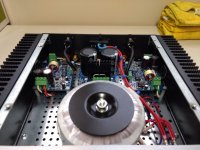
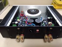
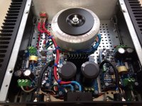
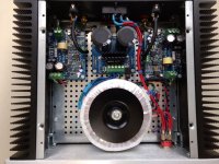
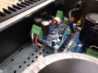
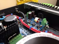
This is my Modulus-86 build into a Mini Dissipante 2U 330mm x 250mm chassis.
It utilizes an Antek AS-2222 and a Power-86.
Even with the modules mounted at one end of the HS, it still runs cool and rarely gets above ambient temp at moderate volume levels.
It utilizes an Antek AS-2222 and a Power-86.
Even with the modules mounted at one end of the HS, it still runs cool and rarely gets above ambient temp at moderate volume levels.
Attachments
-
 IMG_20200813_112459836.jpg245.5 KB · Views: 1,189
 -
 IMG_20200813_112602413.jpg204.3 KB · Views: 1,162
 -
 IMG_20200813_112615227.jpg305 KB · Views: 1,135
 -
 IMG_20200813_112657974.jpg318.9 KB · Views: 1,130
 -
 IMG_20200813_112819136.jpg264.8 KB · Views: 1,106
 -
 IMG_20200813_112831106.jpg253.8 KB · Views: 744
Last edited:
So, if I understand well the lm3886 needs to be soldered at the end?
That's how I do it.
Here's my DIY way of doing it. I'm not suggesting that it's the "right" way or the only way. Only that it is the way that works for me.
- Draw a rectangle with the same dimensions as the insides of the chassis.
- Play around with the PCBs and power supply within this rectangle until a good layout is found.
- Determine the locations of connectors and switches.
- Drill front and rear panels.
- Assemble the chassis (sans top panel, of course).
- Mount connectors and switches.
- Verify that the layout of the boards and power supply still works (no interference with any of the connectors/switches. No surprises).
- Mark the bottom panel with the locations of the mounting holes for the PCBs and power supply. I use the un-populated PCBs as a drill template when marking the hole locations.
- Remove the bottom panel. Drill and de-burr the holes.
- Remount the bottom panel. Add standoffs for the MOD86 PCBs. Mount the bare PCBs to the standoffs.
- Drop the LM3886 into its holes on the PCB. Press it up against the heat sink and mark the location of its mounting hole on the heat sink.
- Remove the heat sink. Drill and tap the mounting hole for the LM3886.
Here's how I get the LM3886 aligned correctly:
- Populate the MOD86 boards, but leave the LM3886 off.
- Assemble the chassis.
- Mount the MOD86 board on standoffs in the chassis.
- Attach the LM3886 to the heat sink with the appropriate mounting hardware.
- Solder 3-4 pins on the LM3886 from the top. Make sure to get a pin at each end of the chip and a pin in each row. This prevents the LM3886 from moving side-to-side and back/forth.
- Remove the MOD86 board. Be careful not to disturb the LM3886.
- Solder the LM3886 from the bottom of the board as normal.
- Remount the MOD86 board. I'd leave the four mounting screws a little loose until the LM3886 has been mounted to the heat sink. Then tighten the four screws.
- Connect the boards. Test. Put a lid on the chassis.
- Crack open a beer (optional).
- Enjoy the music.
The main drawback of this method is all the assembly-disassebly-reassembly needed. The advantage is that you get everything in the right location. This method has worked for me for well over 30 years.
That said, CAD tools are pretty cheap. QCAD Pro is $38 and does everything you need. If you email ModuShop, they'll happily provide the CAD drawings for the chassis. Then all you need to do is to define the cutouts and send the file to ModuShop.
I usually create a layer named Component Outlines where I draw the boards, transformers, etc. to make sure everything fits with a good amount of space between boards and such. That's how I designed the chassis for the Modulus-286 Kit (LE) that you can see in Post #5175. You don't need fancy three-dee renderings if you have half-decent visuospatial skills.
The main drawback of the CAD approach is cost. ModuShop does not work for free. Nor should they. Their fees are actually very reasonable for one-off mechanical work. But expect a chassis with holes to come in around $250-300. Add digital print on the front and/or rear panels and you're closer to $350-400. But, man... It is so nice to receive a chassis that has all the mechanical work done. All you need to do is to drop the components in and turn a screwdriver.
Tom

This is my Modulus-86 build into a Mini Dissipante 2U 330mm x 250mm chassis.
PSA: I suggest covering the mains-connected terminals on the power switch with heat shrink.
Tom
Merci Tom, it's crystal clear
As off today:
I'm waiting the boards to reach my mail box
I'm savouring beers in a lovely area south France while reading and reading and reading your website for my learning knowledge.. But man.. For a newbie like me, when I read 3 pages, I already forget the content of page 1... Beers don't help though...
But I'm making my way..
I'll order from Mouser and other parts when back home.. Easier than with a tiny smartphone...
Thanks..
By the way, I have to mention it as I read it here : Tom's service is faster than Amazon.. I ordered on neurochrome website, received email my order was in.. Two hours later received tracking number hehehe...
I'm waiting the boards to reach my mail box
Tracking says the package is making good progress.
I'm savouring beers in a lovely area south France
Nice. Whereabout? I grew up in Denmark and my folks and I would vacation for 4-5 weeks in France every summer. Mostly in Provence. I visited the past two summers near Aix-en-Pce and was supposed to go again this year, but COVID put a stop to that.
while reading and reading and reading your website for my learning knowledge.. But man.. For a newbie like me, when I read 3 pages, I already forget the content of page 1...
Yeah. I remember feeling like that when I read Douglas Self's article series in Wireless World (what became his book) the first time.
By the way, I have to mention it as I read it here : Tom's service is faster than Amazon.. I ordered on neurochrome website, received email my order was in.. Two hours later received tracking number hehehe...
Heh. That's awesome. Yeah. I prefer to just get the orders boxed up and underway. That way I don't forget. It also turns out it's considered "good service". 🙂
I'm enjoying a cold pilsner and some music after hockey tonight. Good times.

Tom
I'm actually in a tiny village of 50 souls named Planzolle in Ardèche region, it's mountainous/hills surrounded by forest and vineyards, the entire village has been build with local stones, so it's actually cutie.. Tomorrow Saturday hitting Provence! So nice and peaceful there
We had a 3 month home containment due to covid, so we all happy to be free again.. But, but.. News don't seems to be that good for near future.. Let's see.. That **** is still around and freatening...
Whoever wants to visit France, I would recommend Ardèche region : so much to do here with aquatics rivers, charming villages, nice wine and locations or camping are not as expensive as South South France where it sometime get ridiculous... Example, in the the tiny village I am currently, next to the little church, there's this guy making and selling in own beers for only 2 euros the glass..you sit under a tree on a fountain, admire the view, and savour your glass under 40 degrees celcius... You can even buy local bread, cheese and hams to local people... They all smiling and happy.. Funny to see a 70 yo grandpa puffing weed while selling you cucumbers hahaha..
This is my Modulus-86 build into a Mini Dissipante 2U 330mm x 250mm chassis.
It utilizes an Antek AS-2222 and a Power-86.
Even with the modules mounted at one end of the HS, it still runs cool and rarely gets above ambient temp at moderate volume levels.
Do you have a shot of the front of the amp?
What wire did you use for power?
Very Nice Job!
- Home
- Amplifiers
- Chip Amps
- Modulus-86 build thread