Really? Which one? I'm not saying I know different, I just haven't noticed them in their portfolio.
All the Connex Electronic supplies I've recommended for use with the MOD86/286 are regulated.
Tom
This one maybe....?
http://www.connexelectronic.com/documents/SMPS500QRv2.pdf
Interesting. I wonder why they wouldn't just wrap a control loop around it. #whatever Their choice.
The SMPS300RE and SMPS500R that I recommend for use with the MOD86/286 are both regulated. I'd recommend a Hypex one if they made a ±28 V version.
Tom
The SMPS300RE and SMPS500R that I recommend for use with the MOD86/286 are both regulated. I'd recommend a Hypex one if they made a ±28 V version.
Tom
For amplifiers in general, I could imagine a long list of concerns; but, for Tom's amplifier, only one, and that one concern is this:
Supply impedance of rather cheap filters aboard the SMPS, may vary off from expectations. It might not maintain good regulation while driving a load. It is possible that I've described this with wrong language, so here's another try: Generally, it is the marketing specialist (with no electronic education) in charge of advertisement headline figures for SMPS. How much time the headline figure can be used (varies between one second and indefinitely) and how much more noise output happens if you do (if you get close to the headline current or watts figure), tends to vary between makes of SMPS.
Between units that have the same headline figures, outcome can vary across the vast spectrum from useless to excellent (despite same figures printed on the box). It isn't just the two extremes that are available--the middle ground also happens to include some lackluster results. That latter bit is the worst; because, when it is 'slightly off' there's more labor involved in finding out what went wrong.
This might take some careful shopping!
In my experience, Good SMPS are available, they're not the majority and they're never the cheapest.
First post at DIY Audio. I finished my Modulus 86 build and sent Tom an e-mail to let him know how great it sounds. He asked if could share here, and I'm happy to do it.
Hi Tom,
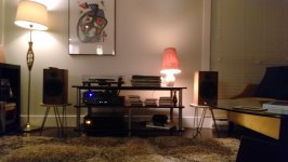
I finally got around to putting your amp into use and I just wanted to write to let you know how great it sounds. I'm using a Benchmark DAC1 HDR as source and ATC SCM11s as speakers. Great depth and imaging, really articulate bass.
I ended up taking a while to do the assembly, then even longer to design an enclosure (I had this made at Protocase, another Canadian company). The last few months of waiting were on getting a phono stage, as I had been using the one in my previous integrated (an old Sansui, restored and recapped to sound pretty good).
I've attached a few photos in case you're interested to see how some of these turn out.
Thanks again for the great amp.
- Jeff
Hi Tom,
I finally got around to putting your amp into use and I just wanted to write to let you know how great it sounds. I'm using a Benchmark DAC1 HDR as source and ATC SCM11s as speakers. Great depth and imaging, really articulate bass.
I ended up taking a while to do the assembly, then even longer to design an enclosure (I had this made at Protocase, another Canadian company). The last few months of waiting were on getting a phono stage, as I had been using the one in my previous integrated (an old Sansui, restored and recapped to sound pretty good).
I've attached a few photos in case you're interested to see how some of these turn out.
Thanks again for the great amp.
- Jeff
Attachments

Connex also sells assemblies that are a PCB with bunch of large-ish caps if you feel you need more capacitance between their SMPS and your amp.
jrleadbet:
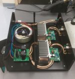
Nice job, very clean, I like the choice of a steel enclosure and the separation of the linear power stage from the active electronics with a steel barrier.
Nice job, very clean, I like the choice of a steel enclosure and the separation of the linear power stage from the active electronics with a steel barrier.
The photos are quite impressive!First post at DIY Audio.
I was fascinated for quite a while on just counting the number of things that were done on purpose. Initially, I was just checking to see if that neat looking amp had both a hot air output and a cool air intake.
Oh it does.
The feet are tall enough to make the cool air intake work well (Sony forgot? that on their HD radio).
And, your amplifier is positioned near floor level, which is cooler.
The amp is also on the side of the shelf away from the Electromode linear convector, which is cleverly sized to most comfortably stabilize the room temp (that costs a fraction as much as freeze-n-burn), and it was ever so neatly installed. I've seen a lot of those, but it is the first time seeing one that made the room look better. I get curious, so is the thermostat at doorknob height and near the seating (so it is never necessary to move the knob)?
Looking beyond the excellent care of the thermals, I also spotted a neat soldering area (other photo).
My own soldering area looks like a small plane full of electronic parts had crash-landed onto large bin of entirely different electronic parts. It isn't that they weren't put away, but they tend to escape if I do more than one project at a time.
And then back to your photos. . . Since there's no TV hooked up to your audio system, it is far more likely to play music. Excellent!
I've had the misadventure of putting a fine sounding system in the same room as a TV, even though yet more TV sound wasn't what I was after. Your photo shows sure cure for it: A nice, quiet, albeit weird, painting; that cannot block off the music like a TV does. Kudos!
One more look at the amp. . . It is built like a tuner in that the power and signal are well separated. That amp didn't require so much care, but it is good to see it built like that.
jrl,
the pigtail connecting Pin1 to enclosure is far too long.
Is the shell of the socket electrically connected to the enclosure?
If not, then make it so. The more electrical connections you can ensure around the perimeter of the hole it pokes through the better.
Then you can connect Pin 1 direct to the shell of the XLR socket with a few strands of wire just 3mm long. 4 strands of 0.15mm diameter cooper 3mm long is far lower impedance than 42 strands of 0.15mm copper that are 30mm long.
Pre-solder the shell with a very hot soldering iron before you solder on the short wires.
You can also attach 10pF to 47pF ceramic capacitors of NP0 type from pin2 to pin3 and from pin1 to pin2 and from pin 1 to pin3. These provide a bit extra RF attenuation before it enters the enclosure. The leads of the caps MUST be very short, 1mm to 2mm maximum.
Last edited:
Alternatively, avoid the pigtail completely by using a Neutrik XLR socket which includes a chassis tab next to pin 1 - NC3FD-LX-BAG
Supply impedance of rather cheap filters aboard the SMPS, may vary off from expectations. It might not maintain good regulation while driving a load.
For sure. The supply impedance and load regulation is something one should look at when buying a power supply. That's in fact why I limit my recommendations to supplies I've tested or that are well specified by the manufacturer.
In my experience, Good SMPS are available, they're not the majority and they're never the cheapest.
That applies in a lot of situations. You often get what you pay for. Except in case of many of the eBay vendors where I'd argue that while you don't pay a lot, you often don't get what you pay for.
Connex also sells assemblies that are a PCB with bunch of large-ish caps if you feel you need more capacitance between their SMPS and your amp.
True that. Some experimentation/characterization may be needed to find the optimal amount of capacitance, though. It all depends on the regulation bandwidth of the regulator and how the additional capacitance plays in.
the pigtail connecting Pin1 to enclosure is far too long.
Is the shell of the socket electrically connected to the enclosure?
If not, then make it so. The more electrical connections you can ensure around the perimeter of the hole it pokes through the better.
I find it funny how you choose to worry about a short pigtail while ignoring all the RF that will enter through the long slots in the top plate. #perspective
You can also attach 10pF to 47pF ceramic capacitors of NP0 type from pin2 to pin3 and from pin1 to pin2 and from pin 1 to pin3. These provide a bit extra RF attenuation before it enters the enclosure. The leads of the caps MUST be very short, 1mm to 2mm maximum.
Actually, by definition, they wouldn't. If you want to keep the RF outside the chassis, you'd need ferrite beads on the outside of the enclosure and feed-through capacitors as the various wires enter the enclosure. You'd also need an RF seal along all edges and no slots in the chassis would be allowed. These measures would be completely appropriate if you were building a satellite, space shuttle, or avionics but would be total overkill and completely unnecessary for residential audio applications.
While I do agree that the RFI filter could work more effectively if placed right on the connector, that complicates assembly unnecessarily. That's why the RFI filter is on the PCB.
Tom
I finally got around to putting your amp into use and I just wanted to write to let you know how great it sounds. I'm using a Benchmark DAC1 HDR as source and ATC SCM11s as speakers. Great depth and imaging, really articulate bass.
Thanks again for the great amp.
Thanks for sharing. I appreciate it.
Tom
Yes, NC3FD-LX ist best for EMC (the unpainted version, that is). Chassis must be conductive (free from paint, etc) in the mounting area as well.
For private DIY creation I think if the amp passes the cell phone test "as is" then no need to worry about better connector and additional filtering at the point of entrance.
Put a dialing cell phone close to the amp, hovering around and getting close to any attached cables, unused connetors, switches/knobs etc. If you get the typical clicking noises at significant volume from the speakers, EMC could be bettered.
Put a dialing cell phone close to the amp, hovering around and getting close to any attached cables, unused connetors, switches/knobs etc. If you get the typical clicking noises at significant volume from the speakers, EMC could be bettered.
For private DIY creation I think if the amp passes the cell phone test "as is" then no need to worry about better connector and additional filtering at the point of entrance.
Put a dialing cell phone close to the amp, hovering around and getting close to any attached cables, unused connetors, switches/knobs etc. If you get the typical clicking noises at significant volume from the speakers, EMC could be bettered.
I agree. In addition, switching sparks from heavy loads turning on (think furnaces, electric heaters, and refrigerators) should not cause clicks in the speakers either.
Tom
Thanks everyone for the feedback. I did spend way too long working out details, so it's nice to hear I caught most of them.
I agree the little pigtails aren't ideal for RF, but I had wanted to use a heavier bolt to make a really strong chassis connection. I noticed the XLR connector does have a pin to the shell, so I could make a direct connection by removing a some of the epoxy finish.
Otherwise, I was a bit careless about RF, as I had seen in Tom's notes there is a filter on the input. The long slots in the enclosure were the biggest compromise; using lots of little circular perforations does a better job, but adds a lot to the enclosure cost.
As is, the amp is super quiet: I can't hear any hiss from the speakers, and music really leaps out of nowhere when I hit play.
I'm still working on the enclosures for my bridged Para 86 amps so currently they are completely open to the domestic elements. Despite that they sound fantastic, which is why I'm completely relaxed about the fact that the only metal in the finished articles will be the heatsinks.
I ran mine in prototype mode (bare boards on heat sink, out in the open) within two feet of my wireless access point right by where I normally put down my cellphone for quite a while. No issues for me either.
That said, I have had LM3886-based amps (P2P setup) where switching transients from the furnace and fridge kicking in would make the amp go 'click'. That's OK for a prototype but unacceptable to me in a finished product.
Tom
That said, I have had LM3886-based amps (P2P setup) where switching transients from the furnace and fridge kicking in would make the amp go 'click'. That's OK for a prototype but unacceptable to me in a finished product.
Tom
So while I have still been a following I have been getting some hours in with the amp and I love it! So much so that I'm confident that it is a solid building block allowing me to look at the speaker and pre-amp options.
My audio chain is currently a RPi with a BOSS DAC (while re-ripping my CD collection to FLAC). A passive preamp based on Arduino controlled LDRs. And the final element is a pair of Furgal Horn MKIIIs with MA Alpair 7P drivers. It does tend to bring out the best and the worst of the sources but I'm find new things in tracks which is what it all about.
Anyways a couple of things...
I'd like to remote power control the amp via the remote of the preamp and I'm thinking a solid state relay would be the ideal way to manage this as it maintains mains isolation and allows low voltage control for easy uP integration. Are there any drawbacks to this approach?
Second and it has been mentioned before, amplifier protection. I'd like to see the power up speaker pops gone (just does not seem profssional) and have the piece of mind that if I (most likely) do something wrong or the amp fails in some way that the speakers are protected while at the same time minimising any impact on the quality of the amp. Any suggestions?
I'd like to see the power up speaker pops gone (just does not seem profssional) and have the piece of mind that if I (most likely) do something wrong or the amp fails in some way that the speakers are protected while at the same time minimising any impact on the quality of the amp.
I don't have power-up pops on my amp. ??? I turn on my amp last and turn it off first and let it decay before powering everything else down.
I'm wondering what is different about our setups.
- Home
- Amplifiers
- Chip Amps
- Modulus-86 build thread