Keep the transformer wiring short as the wires there contain some pretty nasty charging pulses.
Tom
This made me wonder about my proposed layout. Obviously, I'll try this before buying the Dissipante case.
Attachments

I've been a lurker for a while now and still making my way through this thread but thought it time break the posting cherry. I'm upto page 272 so nearly there.
Anyway the result is that I pushed the button two weeks ago to purchase some boards from Tom. At the same time ordered the case and components. As much as for myself I'm going to document my build.
I can cut, bash, solder etc. but don't have hardly any of the skills of the experts here. So if you see anything obviously wrong let me know.
And if you don't mind, I'm going to post the storyboards as I go?...
I'm currently investigating on ways to place legends on the panels while I wait for the boards, cause the moment they turn up the soldering iron will be raring to go.
Thanks for posting your build details, @garym999. I am planning a similar build. I spent the Christmas holidays reading the threads and just ordered my boards. I was considering the same cabinet, too. Meanwhile, I'll keep following here to pick up any more hints and tips.
Layout looks ok. There is always the problem of the incoming mains run. But if you put the trasnformers and the back then you end up with a rear heavy design.
Of course the real angst is that some equipment has power cord at RHS, some at left. Makes dressing cables a pain.
Of course the real angst is that some equipment has power cord at RHS, some at left. Makes dressing cables a pain.
Like this?
I like to keep my XLR input as far away as possible from the AC mains but I'm sure with Tom's design it makes little to no difference if the binding post & XLR positions were exchanged.
Best,
Anand


I like to keep my XLR input as far away as possible from the AC mains but I'm sure with Tom's design it makes little to no difference if the binding post & XLR positions were exchanged.
Best,
Anand
the speaker leads are just as capable as line level leads at picking up interference...................I like to keep my XLR input as far away as possible from the AC mains but I'm sure with Tom's design it makes little to no difference if the binding post & XLR positions were exchanged............
If "special measures" are implemented to improve the line level interference rejection, then you may find that the speaker leads and/or the power supply leads become the dominant route for interference to get into you amplifier.
Layout optimisation in a Mini 300 Dissipante Case
Ok so some things are now fixed ie: the front panel LED and rear panel connectors.
I'm going to have an internal Ali deck so I can provide upper and lower cable runs. Although if I understand what I have read here that many not be much of an advantage, sheilding wise. I was going to have power cables on the underside and speaker and input on top.
Where cables of different types have to cross each other I shall try and to that at right angles to each other.
Tom has suggested that all the power leads should be as short as possible and not reach too far in to the chassis.
So as I see it I have three options, anyone have any thoughts on the best?
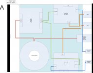
A
- My preferred layout
- Breaks Toms suggestion
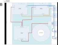
B
- Keeps power on one side
- Heatsinking not optimised
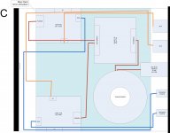
C
- Power cables as short as possible as per Toms thoughts
- Power at rear of case with audio cables having to run around
TIA
Ok so some things are now fixed ie: the front panel LED and rear panel connectors.
I'm going to have an internal Ali deck so I can provide upper and lower cable runs. Although if I understand what I have read here that many not be much of an advantage, sheilding wise. I was going to have power cables on the underside and speaker and input on top.
Where cables of different types have to cross each other I shall try and to that at right angles to each other.
Tom has suggested that all the power leads should be as short as possible and not reach too far in to the chassis.
So as I see it I have three options, anyone have any thoughts on the best?
A
- My preferred layout
- Breaks Toms suggestion
B
- Keeps power on one side
- Heatsinking not optimised
C
- Power cables as short as possible as per Toms thoughts
- Power at rear of case with audio cables having to run around
TIA
Attachments
the speaker leads are just as capable as line level leads at picking up interference.
At RF, that's true. At audio frequencies, it'll be rather hard to move the output node as it is rather low impedance.
Tom
All of those will work.
I suggest you lay these on the bench (no chassis) and actually test/measure the H+N at the output/s. You may find that all perform near enough the same.
You may find that one or two cables need a particular routing to minimise H+N.
When you see a layout that works as well as, or better than all the others, order up a chassis/enclosure that fits around your system layout.
I think you are referring to the output node.At RF, that's true. At audio frequencies, it'll be rather hard to move the output node as it is rather low impedance.
Tom
What about the return cable? It feeds into the -IN node via a many kilo-ohms resistor, sometimes with a low value capacitor across it to take the interference straight into that -IN node.
This made me wonder about my proposed layout. Obviously, I'll try this before buying the Dissipante case.
Tis the same as my prefered, option A. But the suggestion is not to run the power lines to far in to the case and keep them all short. There is a lot going on in your case so I dont see many options I guess you could move the swap the amps to the front and try and get the transformers to the rear so all the power is a the back but then you will have all the amp cables crossing this lot.
I'd say your layout is a good compromise but I know nowt!
So as I see it I have three options, anyone have any thoughts on the best?
None of the above? 🙂
It's preferable to have the amplifier boards centred on the heat sink. Or, specifically, to have the LM3886 IC centred on the heat sink. That said, for a single Modulus-86 channel, scooting the board off centre is not going to break the thermal budget, but I'd keep it within the middle 25-75 % of the heat sink length.
Tom
This made me wonder about my proposed layout. Obviously, I'll try this before buying the Dissipante case.
With the Modulus-286 it is especially important that the board is roughly centred left/right on the heat sink as you show it.
That soft start board is enormous! Is it really that big or is it just a placeholder?
Beware that the connectors on the MOD286 (and PWR86 R1.1) stick out from the PCB, thus, you need probably 50 mm minimum from the board edge to the next object.
Tom
With a large toroidal transformer, there's no good placement, really. This is even more true if a mains filter is used and allowed to protrude into the chassis.
These would be my priorities (roughly in order):
Stuff like power-on LEDs and such is not on the list as it's really quite inconsequential.
I'm not in any way implying that this is an exhaustive list. As with anything else in engineering and audio design, it's a multi-variable optimization problem. There is not likely to be a global optimum. You may find several local optima, each with their own set of tradeoffs.
Tom
These would be my priorities (roughly in order):
- Keep the amplifier boards roughly centred along the length of the heat sink.
- Keep the toroid on the centre line front-to-back of the chassis. That makes the amp much easier to move and tends to work out well with the wiring.
- Keep the transformer wiring short if possible, especially for the secondary.
- Tightly bundle the wires from the power supply to each amplifier board.
- Keep the amp inputs away from high currents (power supply wiring).
Stuff like power-on LEDs and such is not on the list as it's really quite inconsequential.
I'm not in any way implying that this is an exhaustive list. As with anything else in engineering and audio design, it's a multi-variable optimization problem. There is not likely to be a global optimum. You may find several local optima, each with their own set of tradeoffs.
Tom
No, it's really that big! It does include a DC filter, trigger input (from preamp) and thermal protection though.
SoftStart DC
I was going to use vertical variants of the board connectors to allow the boards to be that close.
SoftStart DC
I was going to use vertical variants of the board connectors to allow the boards to be that close.
Yeah, in your case with the 2xMOD286, it may make sense to get the 3U size of the Dissipante. Better thermals. More room. You could flip quite a few of the boards vertical then.
One of my local builders put two Power-86 boards on an angle bracket. That made a nice and compact assembly. You can find his build pictures here: Ed's build.
Here are some examples of nice and compact builds that I happened to stumble upon while digging up Ed's pictures. I'm not saying that other builds aren't "nice" or "compact" as well. Just that these are:
Cowan's build
Curtis' build with internal heat sinks.
Michael's build.
Tom
Last edited:
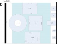
Cheers Tom! Throw another one in why don't you 😛
So now I have a D.
To rephrase my question... I know there are going to be various compromises but what ones are top of the list to consider and what ones are further down the list?
For example the heatsinks are reasonable for the job as long as the amp is not mounted really close to an edge so to that end does the power layout become the more important. Or is it the cable routing etc.
Attachments
Tom, our posts crossed, the list was what I was after, thanks.
I'm stuck with the 2U case so I have no chance to flip boards or tranformers. I'm sure it will be a little clearer when the boards and filter turns up. Also when the boards are populated.
Am I also right in that separating cables either side of the build plate is not going to do much apart from making it look tidyer. The separation is more important.
Looks good to me. I'd probably extend the mezzanine plate to cover the rest of the transformer as well.
Tom
Tom

- Home
- Amplifiers
- Chip Amps
- Modulus-86 build thread