Much more effective improvement you will get with some other transformers instead toroids.
Just measure parasitic capacitance from primary to secondary windings ...
For toroids that is in range of 1000pF.
For EI core depending on winding methods that is in range about 200-500pF
For some 50/60Hz C cores even smaller.
For SMPS with hard-switching 50-200pF (I don't recommend this at all)
For SMPS with soft-switching (resonant LLC) in range of just 5-10pF!!! << Highly recommended!
Larger parasitic capacitance of prim/sec windings means larger coupling with "dirty" mains. 😉
BTW: Did anybody see in any "serious" measuring equipment toroid transformer? 🙂
Last edited:
Hi sebbesen and Tom
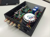
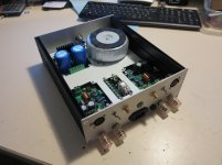
As my amp is mounted (see right photo) and using "Voice of The Theater" very high efficiency loudspeakers (103 dB/W/m), I cannot hear any hum or any other noise at all with my ear in the horn neither from the horn of the TAD TD4001 compression driver.
As Tom said this amp has become my daily amp, by replacing a AN 300B SE.
I have made some listening comparisons with a Nelson Pass Labs X150.5 and a 8W "Le Monstre" by Hiraga.
- I tell you soon...
I see that ebbesen used the case as mine. At home level listening, the aluminium sides remain absolutely cold. At louder level listening they just become a little warmer (~30°C).I do share the concerns about the sides of the chassis being enough heat sink. It won't be for the full dissipation of the LM3886, but it's probably good enough for music reproduction at reasonable volume levels.~Tom
As my amp is mounted (see right photo) and using "Voice of The Theater" very high efficiency loudspeakers (103 dB/W/m), I cannot hear any hum or any other noise at all with my ear in the horn neither from the horn of the TAD TD4001 compression driver.
As Tom said this amp has become my daily amp, by replacing a AN 300B SE.
I have made some listening comparisons with a Nelson Pass Labs X150.5 and a 8W "Le Monstre" by Hiraga.
- I tell you soon...
Attachments
Last edited:
Talking about shielding, I think shielding the circuit makes more sense. At least I found that if I place the circuit in an iron casing, the measured 60hz ac is reduced. This was done with lots of equipment around the bench and looking at the amp output on a scope with lots of other equipment and lighting around. Opened and closed the chassis showed a significant change on the scope.
A Faraday cage (aka grounded metal chassis) will eliminate (read: significantly reduce) the capacitive coupling into the circuit inside the cage. It will, however, do nothing for electromagnetic coupling. See my comment about the skin depth earlier. You'd need incredibly thick walls in the chassis to make a meaningful difference -- unless you're using mu-metal.
~Tom
It was born with genetic abnormality : It is missing a mains switch 🙄It is born...
I did not realize Faraday cages worked at 60Hz.A Faraday cage (aka grounded metal chassis) will eliminate (read: significantly reduce) the capacitive coupling into the circuit inside the cage. It will, however, do nothing for electromagnetic coupling. See my comment about the skin depth earlier. You'd need incredibly thick walls in the chassis to make a meaningful difference -- unless you're using mu-metal.
~Tom
Since the chassis at that time had an iron cover but aluminum base, I used aluminum to cover which did not show the same effect.
I am not sure whether it would have effected sound or not, but it would be an interesting test.
I did not realize Faraday cages worked at 60Hz.
Faraday cages will terminate any electrostatic field lines, hence, they work for capacitive coupling. They will not provide any meaningful attenuation for electromagnetic fields, hence, are not effective against inductive coupling.
Since the chassis at that time had an iron cover but aluminum base, I used aluminum to cover which did not show the same effect.
I am not sure whether it would have effected sound or not, but it would be an interesting test.
Assuming you have a clean measurement setup, it should be relatively straight forward to characterize the effect of the shielding. The challenge is to get a clean setup, i.e. one that doesn't introduce any of the crud you're trying to measure...
~Tom
Somewhat gives the wrong impression, better said isFaraday cages will terminate any electrostatic field lines, hence, they work for capacitive coupling. They will not provide any meaningful attenuation for electromagnetic fields, hence, are not effective against inductive coupling.
To a large degree, though, they shield the interior from external electromagnetic radiation if the conductor is thick enough and any holes are significantly smaller than the wavelength of the radiation.
Hi sebbesen and Tom
At home level listening, the aluminium sides remain absolutely cold. At louder level listening they just become a little warmer (~30°C).
As my amp is mounted (see right photo) and using "Voice of The Theater" very high efficiency loudspeakers (103 dB/W/m), I cannot hear any hum or any other noise at all with my ear in the horn neither from the horn of the TAD TD4001 compression driver.
In your case you are not going to dissipate much at all!. Most of the time you will be tickling along at a few mW. Hope you have a lot of fun with the new Amp.
As ever Frank you miss the important parts to quote. As Tom has posted the graph of metal thickness vs attenuation I am not sure why you are trying to wield wiki in response.
And you're missing what my response was about - my first thought was, Huhhh, Faraday cages are about protecting against electromagnetic effects! Just saying "Faraday cages will not provide any meaningful attenuation for electromagnetic fields" is confusing, certainly for me, so some extension to the point is worthwhile.
try reading this. Its a 1987 JAES paper by Mr Sowter http://atmsp.whut.edu.cn/resource/pdf/4309.pdf gives a nice table of attenuation by frequency on page 15. You can see there that for under 100Hz standard metals provide little useful attenuation, just as Tom said, and as his graph a few pages back showed.
That kind of shielding isn't needed with a very low gain power amplifier. But, you could shield the signal cables.Good point. The wiring is still subject to modification. I'm also considering placing a metal plate between the transformer and the Mod-86 boards to act as a shield.
At post#1430 on the Honey Badger build thread, OStripper shares some ideas on shielding the signal cables.
http://www.diyaudio.com/forums/soli...honey-badger-build-thread-29.html#post4251857
Audio signal is on every cable that connects to the amplifier board. Even so, I think that the small signal cable can be a priority.
However, what I said earlier may be more effective than shielding attempts, and that was:
"I suggest to move the small signal input cables, slightly farther away from the transformer. "
Last edited:
+ 1"I suggest to move the small signal input cables, slightly farther away from the transformer. "
Mod-88 build
What components I need to build a Parallel-88?
* Parallel-86 Amplifier PCB, mono x 2
* Power-86 Power Supply PCB x 1
* Heatsinks x 2
* Toroidal transformer: 230VA, 115VAC or 230VAC (Spain, 230/50Hz) operation, and dual 35V secondaries x 1
* Slow fuse x 1 (or two?)
And box, cables, connectors...
Anything wrong? Anything else?
Serious answers please.
Last edited:
Electrostatic fields can show up at 60Hz? If I repeatedly see a lower level with one cover (iron) and higher level with another (aluminum), seems convincing enough...Faraday cages will terminate any electrostatic field lines, hence, they work for capacitive coupling. They will not provide any meaningful attenuation for electromagnetic fields, hence, are not effective against inductive coupling.
Assuming you have a clean measurement setup, it should be relatively straight forward to characterize the effect of the shielding. The challenge is to get a clean setup, i.e. one that doesn't introduce any of the crud you're trying to measure...
~Tom
Personally I prefer showing shielding to be effective in realistic environments. If I need to be more precise in design, then yes, in a controlled chamber is good. Certification does require controlled environment.
Your explanation seems to suggest that one could use a cell phone in an aluminum room.
Last edited:
The most critical part in Power amplifiers are wires/traces from transformer to diode bridge and to bulk capacitors because the pick current values are about 6x larger than nominal current.
Those large current are prone to emit strong EMI from wires and for that reason we need to take care on that. Also that is a reason why we usually need much higher current rated diode bridge than nominal expected current.
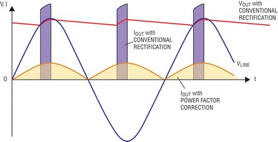
PS: This behaviors can be omitted with 3 phase 12 pulse rectification 🙂 With such rectification you can get about 1,4% of voltage ripple WITHOUT any capacitors!!! Ripple frequency is 600Hz (for 50Hz mains) and we need just small values of capacitors to make it almost perfect 🙂
Take an look on attached PDF schematic ...
Those large current are prone to emit strong EMI from wires and for that reason we need to take care on that. Also that is a reason why we usually need much higher current rated diode bridge than nominal expected current.
PS: This behaviors can be omitted with 3 phase 12 pulse rectification 🙂 With such rectification you can get about 1,4% of voltage ripple WITHOUT any capacitors!!! Ripple frequency is 600Hz (for 50Hz mains) and we need just small values of capacitors to make it almost perfect 🙂
Take an look on attached PDF schematic ...
Attachments
Last edited:
What components I need to build a Parallel-88?
* Parallel-86 Amplifier PCB, mono x 2
* Power-86 Power Supply PCB x 1
* Heatsinks x 2
* Toroidal transformer: 230VA, 115VAC or 230VAC (Spain, 230/50Hz) operation, and dual 35V secondaries x 1
* Slow fuse x 1 (or two?)
I would go with at least 300 VA for the transformer. You can play with the math in the Class AB Output Stage Calculator Excel sheet I have at the bottom of the Taming the LM3886 - Power Supply Design page.
The final rectified voltage needs to be ±35 V. This requires a transformer with 26 VAC secondary. The primary voltage of the transformer needs to match the mains voltage that you will use. Many transformers have dual primaries and you can configure them for 230 V operation by connecting the windings in series. I document how to find the windings and connect them correctly in the documentation for the Power-86 board. I use an Antek AN-series transformer as an example.
The most critical part in Power amplifiers are wires/traces from transformer to diode bridge and to bulk capacitors because the pick current values are about 6x larger than nominal current.
Those large current are prone to emit strong EMI from wires and for that reason we need to take care on that.
Yep. So keep these wires tightly bundled.
Also that is a reason why we usually need much higher current rated diode bridge than nominal expected current.
Actually, the diodes are rated for the average current.
~Tom
PS: This behaviors can be omitted with 3 phase 12 pulse rectification 🙂 With such rectification you can get about 1,4% of voltage ripple WITHOUT any capacitors!!! Ripple frequency is 600Hz (for 50Hz mains) and we need just small values of capacitors to make it almost perfect 🙂
Take an look on attached PDF schematic ...
That's great .... for countries where 3-phase power is commonly brought into residential areas. In North America, we operate with 120-0-120 V center tapped pole transformers. I'd need to have the power company route a new feeder to my house to get 3-phase power, if it's available at all.
~Tom
Avel Lindberg - Toroidal Transformers
Avel Lindberg
Transformers and Power Converters From Avel Lindberg, Inc.
Parts-Express Avel Lindberg - Toroidal Transformers With A Power Range from 30VA to 800VA
-> Avel Y236801 500VA 25V+25V Toroidal Transformer $87
Avel Lindberg
Transformers and Power Converters From Avel Lindberg, Inc.
y23_range_specs.htm.Y23 Standard Range General Specifications
Primaries: 115V + 115V. Frequency: 50/60 Hz.
High pot: tested at 4K VRMS.
Secondary voltage tolerance: Within 3% at normal input and full load.
Mounting hardware: Metal dish, 2 foam pads, bolt, washer, and nut included with each transformer.
Leads: 150 mm / 6" (±5 mm / .2") stranded, PVC insulated.
Double-insulated primary leads: UL1672 (105º C, 300 V).
Secondary leads: UL3266 (125º C, 300 V)
Clearance: allow 4 mm / .2" over mounting hardware.
Certifications: UL506/CSA 22.2, No. 66; CE marked and tested in accordance with EN61558 (replacing EN60742), EN60065, EN60950, BS415, VDE0550. Also available: UL1411/CSA 22.2 No. 1-94; UL1950/CSA 22.2 No. 950-95; UL2601 (UL544)/CSA 22.2 No. 601.1.
Parts-Express Avel Lindberg - Toroidal Transformers With A Power Range from 30VA to 800VA
-> Avel Y236801 500VA 25V+25V Toroidal Transformer $87
An externally hosted image should be here but it was not working when we last tested it.
Last edited:
- Home
- Amplifiers
- Chip Amps
- Modulus-86 build thread