Bob if You buy tc from audiophonics.fr and if more people participate you almost eliminate delivery charge from france. And only postage from uk will cost you, but approximate ratio of weight to cost is not rising sharply with adding more caps into package. Consider redistributing caps from single Address in usa. On Other hand sending small packets my slip through customs unnoticed.
Sorry to interrupt the caps discussion.
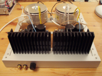
Here is a quick photo of amplifier on a chassis. Heard hum for the first time when swiched it on after mounting. Cause - the crappy RCA sockets and bad contact. While the DACT type attenuator and CMS RCAs are being shipped from China the similar size low quality warn out equivalents are installed for design evaluation. A bit of rocking and rolling of the plugs eliminated the hum.
Here is a quick photo of amplifier on a chassis. Heard hum for the first time when swiched it on after mounting. Cause - the crappy RCA sockets and bad contact. While the DACT type attenuator and CMS RCAs are being shipped from China the similar size low quality warn out equivalents are installed for design evaluation. A bit of rocking and rolling of the plugs eliminated the hum.
Attachments
Here is a quick photo of amplifier on a chassis.
Interesting... why RCAs are in front, near the volume pot? An original placement.
Heard hum for the first time when swiched it on after mounting. Cause - the crappy RCA sockets and bad contact.
(...)
A bit of rocking and rolling of the plugs eliminated the hum.

Often this is the main caus of hum...
O.K. Anyone in U.S or Canada please PM me and I will start a list. We will determine what advantage can be gained based on the number of participants..
Before collecting money I suggest you to wait a week or two.
I've ordered Suburra's suggested Clarity Cap MR (available also from PCX) which can be fitted on 1.02 boards and are a perfect fit for 1.05 boards.
If he's right they should be on par if not better than TC.
Its just that RCAs are more accessible that way. Easy to connect various sources when needed. And the signal wires are kept short. I tried this configuration on previous devices and came to like it.Interesting... why RCAs are in front, near the volume pot?
DC Speaker Protection
I have been studying and modifying the speaker protection circuit that is common to the FE and all MyRef amps. I am hoping that some of you more experienced guys will take a look at my circuit and comment, offer suggestions, etc.
Since there are a lot of MyRef boards out there, my goal was to modify and improve the performance based on the existing circuit, rather than reinvent it. In my opinion, the circuit allows more DC voltage that I would like before opening the relay and protecting the speaker. Also, depending on the transformer powering it, a much larger negative DC voltage may be required to open the relay. My goal was a lower DC voltage for relay open and a robust opening on negative voltage.
I put this circuit together on a breadboard and tested it with my FE transformer and a DC bench supply. The circuit opened the relay at +5.7 V DC but did not open the circuit to the -13 V DC limit of my bench supply.
https://www.circuitlab.com/circuit/g9cu22/fe-speaker-protection-jac/
This link takes you to a schematic of the modification that I came up with. Click on "Open in Editor" to see the schematic more clearly.
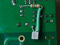
Compared to the FE speaker protection circuit, this circuit modifies one resistor value, removes one resistor, and adds a PNP transistor in series with a resistor. The photo below shows my modified circuit added to the bottom of my FE RC boards.
diyAudio
Positive DC voltage relay opening depends on the DC voltage present at the base of Q3. When it reaches approximately 0.66 V, the transistor turns "on" and drops the voltage at the base of Q2 which turns it "off". Q3 base voltage is determined by the voltage divider formed by R15 and R19. Using the current 75k and 10k, theory suggests that Q3 will turn on at a speaker DC of 5.6 V. Increasing the value of R19 will allow Q3 to turn on at a lower speaker voltage. I selected R19 at 47k for a theoretical Q3 switch at 1.7 V. Other choices could be made. For example, R19 at 33k would give 2.2 V Q3 switching.
Since the negative voltage switching is going to be handled by a new transistor, Q4, there is no need for R16 so it is removed. This provides a potential benefit of more isolation between the speaker signal and the power supply.
Q4 is a 2N4403, a commonly available PNP transistor.
The emitter of Q4 is fed by the junction between Q1 and Q2. When DC voltage at the junction of R15 and R19 is more negative than the emitter of Q4 by about 0.66 V, Q4 turns "on" which connects the base of Q1 to ground. That causes Q1 and the relay to turn "off". When speaker DC is zero and the relay is "on", the base of Q1 is at about 0.66 V. That means that Q4 is already very close to turning on. R24 is added between Q1 base and Q4 emitter to require a bigger negative DC voltage at Q4 base. This can be tuned to your choice. I found that 150 Ohms made the positive and negative DC voltages for relay open to be approximately equal. In my case the relay opens at a measured +1.5 V and -1.7 V DC.
I have been running this modification on my RC boards for long enough to be confident that it doesn't cause any problems in normal use. I would be grateful for any input on this design.
Jac
I have been studying and modifying the speaker protection circuit that is common to the FE and all MyRef amps. I am hoping that some of you more experienced guys will take a look at my circuit and comment, offer suggestions, etc.
Since there are a lot of MyRef boards out there, my goal was to modify and improve the performance based on the existing circuit, rather than reinvent it. In my opinion, the circuit allows more DC voltage that I would like before opening the relay and protecting the speaker. Also, depending on the transformer powering it, a much larger negative DC voltage may be required to open the relay. My goal was a lower DC voltage for relay open and a robust opening on negative voltage.
I put this circuit together on a breadboard and tested it with my FE transformer and a DC bench supply. The circuit opened the relay at +5.7 V DC but did not open the circuit to the -13 V DC limit of my bench supply.
https://www.circuitlab.com/circuit/g9cu22/fe-speaker-protection-jac/
This link takes you to a schematic of the modification that I came up with. Click on "Open in Editor" to see the schematic more clearly.
Compared to the FE speaker protection circuit, this circuit modifies one resistor value, removes one resistor, and adds a PNP transistor in series with a resistor. The photo below shows my modified circuit added to the bottom of my FE RC boards.
diyAudio
Positive DC voltage relay opening depends on the DC voltage present at the base of Q3. When it reaches approximately 0.66 V, the transistor turns "on" and drops the voltage at the base of Q2 which turns it "off". Q3 base voltage is determined by the voltage divider formed by R15 and R19. Using the current 75k and 10k, theory suggests that Q3 will turn on at a speaker DC of 5.6 V. Increasing the value of R19 will allow Q3 to turn on at a lower speaker voltage. I selected R19 at 47k for a theoretical Q3 switch at 1.7 V. Other choices could be made. For example, R19 at 33k would give 2.2 V Q3 switching.
Since the negative voltage switching is going to be handled by a new transistor, Q4, there is no need for R16 so it is removed. This provides a potential benefit of more isolation between the speaker signal and the power supply.
Q4 is a 2N4403, a commonly available PNP transistor.
The emitter of Q4 is fed by the junction between Q1 and Q2. When DC voltage at the junction of R15 and R19 is more negative than the emitter of Q4 by about 0.66 V, Q4 turns "on" which connects the base of Q1 to ground. That causes Q1 and the relay to turn "off". When speaker DC is zero and the relay is "on", the base of Q1 is at about 0.66 V. That means that Q4 is already very close to turning on. R24 is added between Q1 base and Q4 emitter to require a bigger negative DC voltage at Q4 base. This can be tuned to your choice. I found that 150 Ohms made the positive and negative DC voltages for relay open to be approximately equal. In my case the relay opens at a measured +1.5 V and -1.7 V DC.
I have been running this modification on my RC boards for long enough to be confident that it doesn't cause any problems in normal use. I would be grateful for any input on this design.
Jac
Attachments
Before collecting money I suggest you to wait a week or two.
I've ordered Suburra's suggested Clarity Cap MR (available also from PCX) which can be fitted on 1.02 boards and are a perfect fit for 1.05 boards.
If he's right they should be on par if not better than TC.
Hi D,
I'm not collecting money, just looking for the level of interest. That new cap information sounds very encouraging and we all will be waiting for your review.
Those chinese inlets you linked would be a nice value if they're really copper but often what they call copper is brass with high (?) copper content...
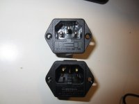
I've ordered those Sonarquest inlets and they're finally arrived.
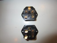
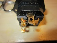
While similar to Furutech FI-03 they're not identic and Sonarquest metal parts are not copper as stated:
I've scraped with a file the gold plating and found plain brass (as the yellowish color demonstrate)
BTW, how they sound?
Not bad at all but Furutechs sound fuller and less dry.
On GD-Audio eBay store you can find the very same IEC but not gold plated, it costs about a third and honestly it's declared as brass...
IEC make a tiny difference, I would categorize them as extreme tweakings.
If you're interested in such extremes buy from reputable manifacturers like Furutech...

Attachments
Last edited:
Jac, Along with being able to adjust the timing with your design, are you saying the lower DC also adds a significant measure of protection for the speakers - makes them potentially less vulnerable?
Bob,
Actually, this isn't so much about adjusting the timing. It is mainly about better protecting the speakers by kicking out the relay at lower DC. The nice thing is that you can do the mod to any existing FE board.
It adds a slightly higher level of isolation between the power supply and speaker signal, but I haven't heard any difference.
Of course, it would be great if somebody with a better knowledge of circuits and transistors comments. I could easily have missed something.
Jac
Thanks Jac, sounds interesting. I'll await further comment also.
No "Wire Wars" please - but Dario, since you are in the neighborhood, what's your current preference for mains wire from the inlet to the transformer/softstart - assuming there is a significant distance? Have you detected any audible differences?
No "Wire Wars" please - but Dario, since you are in the neighborhood, what's your current preference for mains wire from the inlet to the transformer/softstart - assuming there is a significant distance? Have you detected any audible differences?
You bought cheapo parts from China and they're not what they claim? Who could be surprised by that? I've fallen for that trick a few times myself, but NEVER again.
I believe AC mains wire does not affect sonics as much as AC mains connectors. Just my opinion.
I also have an opinion on the sound of Clarity MR. I recently replaced a pair of Auricap output caps in a friend's tube DAC. The Clarity MR is definitely superior to the Auricaps. It is a very good metalized poly cap, with decent spatiality and accurate tonality, but just a bit laid back. It does not do anything wrong to the music, but, as far as I could tell (not an exact comparison), it is not the equal of the film/copper foil TC. I'm sure the differences are subtle, but I think the TC is more vivid without being colored, fuller without being fat, a bit more spacious with slightly better layering and separation. For the 1.0uf value, the MR is cheaper by a few bucks, if that's really important. For larger values, it would serve very well, with performance nearly equal to caps costing far more.
I am interested in your impressions after making a direct comparison between them.
Peace,
Tom E
Hey Tom,
I made a pair of these Beldon 8303 and can detect enough improvement that I feel it was worth the effort - not a lot but detectable. My intention was to also use the Belden inside the box, but the wires are very stiff and not easy to use there.
What I have defaulted to till I get more information is to strip out the wires from a good standard PC mains cable and use those, or use the trimmings from the transformer in that build if they are long enough. Another element is the use of screw terminal blocks to facilitate easy disconnection till a permanent/final chassis installation is made. Don't know if using something like a gold plated set would make a difference in the mains path. It seems to me that unless one insures that the metal used in a mains switch and the fuse (even if part of a quality AC inlet) are carefully selected, there is still a fly in the buttermilk.
A screw down terminal is accepted as a "gas tight" connection.
This is the same description applied to a crimped connection when the correct tool is used with the correct terminal with the correct cable.
Screw down is much more tolerant of small changes in terminal size and cable size.
This is the same description applied to a crimped connection when the correct tool is used with the correct terminal with the correct cable.
Screw down is much more tolerant of small changes in terminal size and cable size.
- Home
- Amplifiers
- Chip Amps
- My_Ref Fremen Edition - Build thread and tutorial