I have a stupid question .
I replaced the drivers again with A1220 and C2690 and had the same problem with the waveforms .
I replaced the 47 ohm gate resistors with 33 ohm and the drive looks perfect now
Why would lowering the gate value make the drive perfect now ?
I’m using IRFZ44N’s
I replaced the drivers again with A1220 and C2690 and had the same problem with the waveforms .
I replaced the 47 ohm gate resistors with 33 ohm and the drive looks perfect now
Why would lowering the gate value make the drive perfect now ?
I’m using IRFZ44N’s
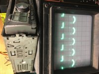
Ok the first pic is of the waveform on the gate leg of the power supply fet .
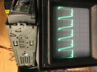
The 2nd image is with a fet in the amp and on the drain leg of the fet .
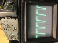
The 3rd image is on the drain leg for the fet the fet is removed out of that location .
The 2nd image is with a fet in the amp and on the drain leg of the fet .
The 3rd image is on the drain leg for the fet the fet is removed out of that location .
Attachments
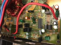
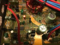
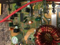
Let me know if you need more pics or better pics of a certain area
Attachments
-
 F7488B08-D550-45D1-BCDF-1E2F34EE9C18.jpg947.5 KB · Views: 31
 -
 26353D3B-F00E-43C9-A703-2D52D955F74B.jpg1 MB · Views: 34
 -
 607EDE04-4EF1-4214-B359-15CB31316853.jpg981.9 KB · Views: 26
 -
 B03EC3A6-5FE7-4D2D-9E06-37AD637A37DA.jpg980.3 KB · Views: 30
 -
 458B6522-D2C1-484A-90BE-A7D42D843880.jpg943.4 KB · Views: 25
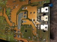
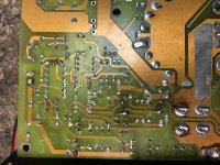
From what I can see, I don't see any problems. I'm assuming that you've made sure that you have good connections, top and bottom where pads are damaged.
With only 1 bank loaded, you can't expect normal drain waveforms.
Go back to the loading cap. At what point do you lose the perfect square wave on the following points. This is one half. Check both halves.
pin 9/10
gate of drivers
emitter of drivers
driver side of gate resistors
FET/cap side of gate resistors
What happened to the perfect waveform you had when you went to 33 ohms?
I’m losing the perfect square wave at the emitter (leg 1) of the drivers .
Maybe I was wrong when I said I had the perfect wave at the fet at 1 point .
And I’m going to confirm I have connection at the top and bottom of board where pads are missing . Which I will fix once I figure out the drive issue
Maybe I was wrong when I said I had the perfect wave at the fet at 1 point .
And I’m going to confirm I have connection at the top and bottom of board where pads are missing . Which I will fix once I figure out the drive issue
Ok figured that out pin 13 had a broken solder connection .
The led for The power light was shorted causing pin 16 to go high .
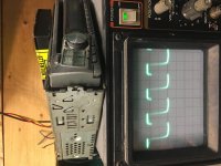
After going through the entire power supply section here is what I get on the gates of the power supply fets this is with it loaded with a fet .
Scope settings are 10us 5 volts /div
Do I still have a problem or does this appear to look good .
The led for The power light was shorted causing pin 16 to go high .
After going through the entire power supply section here is what I get on the gates of the power supply fets this is with it loaded with a fet .
Scope settings are 10us 5 volts /div
Do I still have a problem or does this appear to look good .
Attachments
- Status
- This old topic is closed. If you want to reopen this topic, contact a moderator using the "Report Post" button.
- Home
- General Interest
- Car Audio
- Audio Art 260.6XE