I have a stupid question .
I replaced the drivers again with A1220 and C2690 and had the same problem with the waveforms .
I replaced the 47 ohm gate resistors with 33 ohm and the drive looks perfect now
Why would lowering the gate value make the drive perfect now ?
I’m using IRFZ44N’s
I replaced the drivers again with A1220 and C2690 and had the same problem with the waveforms .
I replaced the 47 ohm gate resistors with 33 ohm and the drive looks perfect now
Why would lowering the gate value make the drive perfect now ?
I’m using IRFZ44N’s
Ok something is not right at all in this amp .
I will take some pics of the waveforms and show you what I have on the fets .
I will take some pics of the waveforms and show you what I have on the fets .
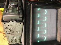
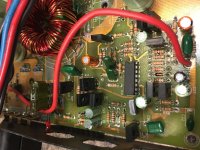
Ok the first pic is of the waveform on the gate leg of the power supply fet .
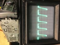
The 2nd image is with a fet in the amp and on the drain leg of the fet .
The 3rd image is on the drain leg for the fet the fet is removed out of that location .
The 2nd image is with a fet in the amp and on the drain leg of the fet .
The 3rd image is on the drain leg for the fet the fet is removed out of that location .
Attachments

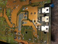
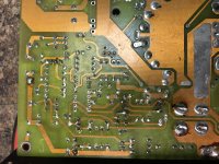
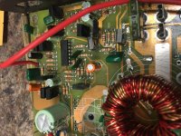
Post good quality photos of the PS section showing the entire drive section and both banks of FET locations, top and bottom.
Let me know if you need more pics or better pics of a certain area
Attachments
-
 F7488B08-D550-45D1-BCDF-1E2F34EE9C18.jpg947.5 KB · Views: 86
 -
 26353D3B-F00E-43C9-A703-2D52D955F74B.jpg1 MB · Views: 60
 -
 607EDE04-4EF1-4214-B359-15CB31316853.jpg981.9 KB · Views: 73
 -
 B03EC3A6-5FE7-4D2D-9E06-37AD637A37DA.jpg980.3 KB · Views: 52
 -
 458B6522-D2C1-484A-90BE-A7D42D843880.jpg943.4 KB · Views: 82
From what I can see, I don't see any problems. I'm assuming that you've made sure that you have good connections, top and bottom where pads are damaged.
With only 1 bank loaded, you can't expect normal drain waveforms.
Go back to the loading cap. At what point do you lose the perfect square wave on the following points. This is one half. Check both halves.
pin 9/10
gate of drivers
emitter of drivers
driver side of gate resistors
FET/cap side of gate resistors
What happened to the perfect waveform you had when you went to 33 ohms?
I’m losing the perfect square wave at the emitter (leg 1) of the drivers .
Maybe I was wrong when I said I had the perfect wave at the fet at 1 point .
And I’m going to confirm I have connection at the top and bottom of board where pads are missing . Which I will fix once I figure out the drive issue
Maybe I was wrong when I said I had the perfect wave at the fet at 1 point .
And I’m going to confirm I have connection at the top and bottom of board where pads are missing . Which I will fix once I figure out the drive issue
I give up on this amp I went thru the entire power supply section and tested resistors drivers diodes transistors and everything checks good .
Used the caps and loaded it same issue I do not get good drive
Used the caps and loaded it same issue I do not get good drive
At this point I’m gonna continue troubleshooting this amp . I will post back once I do some more testing and see where the problem is.
I already have hours invested into it might as well keep going .
I already have hours invested into it might as well keep going .
You stated that you lost signal at the emitters of the drivers.
All 4 drivers?
Signal present there or not present there?
Do you have a solid 12v on both NPN driver collectors and solid ground on both PNP driver collectors?
All 4 drivers?
Signal present there or not present there?
Do you have a solid 12v on both NPN driver collectors and solid ground on both PNP driver collectors?
I’m still going through the power supply .
I found a leaky transistor and a bad trace .
I will go through the other half and update you
I found a leaky transistor and a bad trace .
I will go through the other half and update you
Anyone have a schematic for this amp ?
I can’t figure it out now it has new problems it’s stuck in protection even with the regulators removed
I can’t figure it out now it has new problems it’s stuck in protection even with the regulators removed
Did you mean rectifiers?
Post the DC voltage on all terminals of the TL494 if no one has a diagram.
Pin 1:
Pin 2:
Pin 3:
Pin 4:
Pin 5:
Pin 6:
Pin 7:
Pin 8:
Pin 9:
Pin 10:
Pin 11:
Pin 12:
Pin 13:
Pin 14:
Pin 15:
Pin 16:
Post the DC voltage on all terminals of the TL494 if no one has a diagram.
Pin 1:
Pin 2:
Pin 3:
Pin 4:
Pin 5:
Pin 6:
Pin 7:
Pin 8:
Pin 9:
Pin 10:
Pin 11:
Pin 12:
Pin 13:
Pin 14:
Pin 15:
Pin 16:
Pin 1:1.04
Pin 2:3.49
Pin 3:4.71
Pin 4:0.17
Pin 5:1.43
Pin 6:3.46
Pin 7:0.00
Pin 8:13.91
Pin 9:0.00
Pin 10:0.00
Pin 11:13.90
Pin 12:13.90
Pin 13:0.00
Pin 14:4.90
Pin 15:0.19
Pin 16:1.09
Pin 2:3.49
Pin 3:4.71
Pin 4:0.17
Pin 5:1.43
Pin 6:3.46
Pin 7:0.00
Pin 8:13.91
Pin 9:0.00
Pin 10:0.00
Pin 11:13.90
Pin 12:13.90
Pin 13:0.00
Pin 14:4.90
Pin 15:0.19
Pin 16:1.09
There are a couple of problems. Pin 13 should be tied to pin 14.
Pin 15/16 are causing the PS to shut down. Pin 16 has to be lower than pin 15. When unused, pin 15 is often tied to pin 14 and pin 16 is connected to pin 7.
Pin 15/16 are causing the PS to shut down. Pin 16 has to be lower than pin 15. When unused, pin 15 is often tied to pin 14 and pin 16 is connected to pin 7.
Pin 16 connects through a resistor to the base of a transistor .
Should this transistor be a npn or pnp do you know by chance ?
Wondering if I put the wrong one in that location
Should this transistor be a npn or pnp do you know by chance ?
Wondering if I put the wrong one in that location
Ok figured that out pin 13 had a broken solder connection .
The led for The power light was shorted causing pin 16 to go high .
After going through the entire power supply section here is what I get on the gates of the power supply fets this is with it loaded with a fet .
Scope settings are 10us 5 volts /div
Do I still have a problem or does this appear to look good .
Attachments
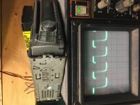
It's a little odd but it could be OK. Is the amp drawing excessive current when the FETs are in the circuit?
- Home
- General Interest
- Car Audio
- Audio Art 260.6XE