Okay so I was given this Audiopipe 1500.1 and it was stuck in protect upon testing I found that the power supply and output mosfets tested okay along with the rectifiers so I pulled the rectifiers out of the board and the amp stayed in protect so I pulled all mosfets from the board and it was still in protect. I found I had one bad rail cap after taking the rail caps off the board the amp powered on. However after putting new rail caps and one power supply mosfet per Bank and the recitfiers back in the amp protects. So i pulled the rail caps back out and it stayed in protect But when I pull the rectifiers out of the amp it powers on fine. So ive been trying to troubleshoot and took quite a few things off or replaced and nothing seems to work I have replaced the power supply and output side driver transistors also taking the driver board off I also disconnected the output inductor nothing changed it but as soon as I take the rectifiers off the amp it will Power back on. I've replaced most of the common things that fail on these amps I've searched threw different threads trying different techniques I've read and still have had no luck getting it to power up with rectifiers in. Even if take the rectifiers out and put the output fets in it goes in protect as well so I feel something is shorted on the rails but I can't figure out what it is. So I'm wondering do I have a messed up Transformer I've tried moving them to see if anything change but doesn't seem to change anything and the power supply mosfets were not blown that were in the amp when I got it. so at this point I'm reaching out for help.
Last edited:
How many people have an isolation transformer?
Add to that that you put all metal parts of your scope at rail voltage when doing this.
There are better ways (using a battery powered scope, no rail voltage, using scope in differential mode...).
https://download.tek.com/document/51W_10640_1.pdf
Add to that that you put all metal parts of your scope at rail voltage when doing this.
There are better ways (using a battery powered scope, no rail voltage, using scope in differential mode...).
https://download.tek.com/document/51W_10640_1.pdf
Last edited:
For most all testing using a scope with car audio, leave the scope ground connected to the 12v power supply negative/ground terminal.
For some tests on the secondary/audio drive signals, you will need to ground to the source leg of the output FETs. For low-side testing, you can generally just use the 12v ground for you scope. For the high side (with no rectifiers and the rail caps discharged - best done before desoldering the rectifiers), you will ground the scope (with the short alligator-clip lead that snaps into the probe) to the source leg of the high-side FETs. If that makes you nervous, connect a wire jumper across the positive and negative speaker terminals. That's generally good enough of a ground for initial testing.
Again, all of this is with the rectifiers out of the circuit.
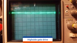
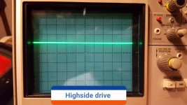
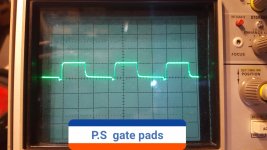
Ok on the high side with the probe ground on the source leg and probe on the gate leg also wire jumper on speaker terminals I get just a tad over 1 volt as shown in pic below.
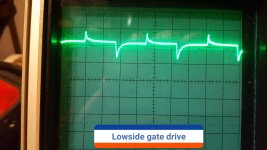
Now on the lowside if I ground to -12v terminal i get what was shown in tbe previous pic of the lowside but if I try to put probe ground on the source leg it goes straight to protect Is that normal.
By the way the rail caps are not in at the moment if that matters.
Now on the lowside if I ground to -12v terminal i get what was shown in tbe previous pic of the lowside but if I try to put probe ground on the source leg it goes straight to protect Is that normal.
By the way the rail caps are not in at the moment if that matters.
Attachments
Perry it does the same thing with the rail caps if i put them back in it with the rectifiers still out it goes into protect.
When I pull the rail caps back out the amp powers on.
The filter rail caps are out as well.
But I just wanted to let you know this just in case it's helpful
When I pull the rail caps back out the amp powers on.
The filter rail caps are out as well.
But I just wanted to let you know this just in case it's helpful
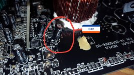
No I didn't see any from the rail caps however there was a small cap labeled c82 that leaked on board and messed up the threw hole connection so I cleaned it with 91% isopropyl alcohol and left the new cap longer so I could solder the trace from the top of the board.
The rails caps did pull most of there vias when I took them out even with lots of heat they still pulled out so I had to reconfigure them so I could solder there leads from the top and bottom of the board for a proper connection as seen below.
Pics below
The rails caps did pull most of there vias when I took them out even with lots of heat they still pulled out so I had to reconfigure them so I could solder there leads from the top and bottom of the board for a proper connection as seen below.
Pics below
Attachments
For anyone reading this, do not pull caps, especially snap-mount caps (large, rigid terminals) unless you absolutely have to.
The problem of going into protection may simply be a random occurrence and not associated with the caps.
See what you can do to git it to power up to get to read the waveforms.
Is there any DC on the output of the amp?
It looks like you have an output installed. Did you have all of them removed when you were trying to get it to power up?
I had to pull the rail caps back out in order for the amp to power on and I got 0.0 VDC on the output terminals.
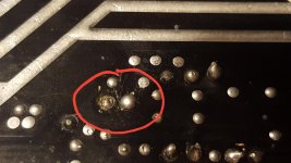
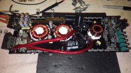
There is no outputs in the amp the mosfet in picture is on the power supply as shown in the picture below.
I pulled the rails cap last after left with no other option and found one was shorted and the amp powered up.
But if I put the rectifiers, output fets, rail caps back in the amp in any order the amp will protect.
Attachments
Pin 1: 4.99
Pin 2: 7.22
Pin 3: 0.058
Pin 4: 0.00
Pin 5: 1.466
Pin 6: 3.582
Pin 7: 0.00
Pin 8: 12.06
Pin 9: 5.127
Pin 10: 5.113
Pin 11: 12.06
Pin 12: 12.06
Pin 13: 4.99
Pin 14: 4.99
Pin 15: 2.045
Pin 16:0.004
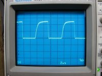
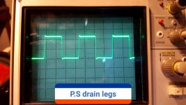
Power supply waveforms in pics below.
Pin 2: 7.22
Pin 3: 0.058
Pin 4: 0.00
Pin 5: 1.466
Pin 6: 3.582
Pin 7: 0.00
Pin 8: 12.06
Pin 9: 5.127
Pin 10: 5.113
Pin 11: 12.06
Pin 12: 12.06
Pin 13: 4.99
Pin 14: 4.99
Pin 15: 2.045
Pin 16:0.004
Power supply waveforms in pics below.
Attachments
- Status
- This old topic is closed. If you want to reopen this topic, contact a moderator using the "Report Post" button.
- Home
- General Interest
- Car Audio
- Audiopipe AP1500D issue