SSS,
Your idea is good. Primary mosfets sure flows alot of current. So if your purpose is exact current sharing, maybe this is better. If you have like 5 mosfets per side in primary, arrange the wires so it can be divided by 5, like 5 wires or 10 wires in half side of primary. Then place 1 (or 2 if total = 10) as near as the drain of the mosfet. But between 5 drains still have connection (not independent, but dont have to be heavy tracks). This way you can put minimum path between each mosfets to the primary wires, have better current sharing for each mosfets, but you still have connection between each mosfets drain so it is more safe than having those mosfets independent (drain not attached to each other)
Your idea is good. Primary mosfets sure flows alot of current. So if your purpose is exact current sharing, maybe this is better. If you have like 5 mosfets per side in primary, arrange the wires so it can be divided by 5, like 5 wires or 10 wires in half side of primary. Then place 1 (or 2 if total = 10) as near as the drain of the mosfet. But between 5 drains still have connection (not independent, but dont have to be heavy tracks). This way you can put minimum path between each mosfets to the primary wires, have better current sharing for each mosfets, but you still have connection between each mosfets drain so it is more safe than having those mosfets independent (drain not attached to each other)
audio power smps
If you aim is audio power by smps pls check this site;www.audiopowerelectronics.com patents/papers.
If you aim is audio power by smps pls check this site;www.audiopowerelectronics.com patents/papers.
Re: audio power smps
the links are dead
soundbag said:If you aim is audio power by smps pls check this site;www.audiopowerelectronics.com patents/papers.
the links are dead

It means he and I cannot reach it. Maybe even you cannot reach it.How do you mean, the link is dead?
www.audiopowerelectronics.com
Well, well, well,
If you can not reach the site, may be you should try through yahoo search or google search, because I have just open the same sight now, and it works perfectly from the address I gave on the forum.
In the main time try another site, www.switchingpowermagazine.com and read vol.5 issue l. by the the same owner of www.audiopowerelectronics.com on the topic "switching power in audio".
The author Eric Mendenhall, is the designer of qsc audio smps for powerlight 6 and 9., and other 6 companies as a worker and consultant.
Try the sites again pls.
Hello all.
This message is for EVA:
Hola! Me alegro de ver otra española en el fórum!
Well, back to english.
EVA, I am the co-author of Rod Elliot's Project 89. I wrote it a couple of years ago and I have had the opportunity to see that since then many people has shown interest on this kind of circuits as it was very difficult for me to find information on the Internet these days!
I think it has been demonstrated that you have quite a good amont of experience with toroids for car smps. I agree with you in that almost all designs are based on toroids.
Could you please post here some rules of thumb in order to wind a good toroid? I wound a good amount of them until I got what I wanted, but a summary here could be of great utility.
I think that we could even add your ideas (and name) to the ESP article, for future reference, what do you think?
If you want, you can contact me at ssanmor@canal21.com
Thanks!
the best torroid winding advice for DIYr's is probably to be found in the ARRL HAndbook -- and these are in libraries all over the world.
While almost all manufacturers have all of the data sheets for ferrites and powder cores on their websites, www.amidoncorp.com actually has some information on how to use the data. there are a number of problems to be solved in designing the coil or transformer -- fortunately we as DIYr's don't have to go through some elaborate linear programming process to optimize design efficiency vs price -- bigger just costs a little bit more!
wasn't someone going to write an article for AudioXpress on this topic?
I think that project 89 has some of room for improvement and I would like to redesign it, but I'm somewhat busy now with other tasks
I also have a non dissipative phase-sweept soft-start prototype that Rodd Elliot may find attractive. I think this technique uses less space and is cheaper and more reliable than classic relay and big resistor implementations
I also have a non dissipative phase-sweept soft-start prototype that Rodd Elliot may find attractive. I think this technique uses less space and is cheaper and more reliable than classic relay and big resistor implementations
Hello, Eva.
Nice to hear from you.
Of course the ESP article can be improved a lot. As I said, it was written 2 years ago, and now there is a lot more of useful info over there that could be included.
If you want to collaborate we could add value to the project 89, to make it more useful for DIYers. For example, a extensive description of transformer winding could be very useful.
I am open to your comments.
Best regards,
Sergio

MAINS POWERED SMPS of about 1KW or more is my purpose. I have build the driver schematics of it but of course my problem is the power transformer (no core available  ). I'l order one from some manifacturer if I could'n get some good one in my country in the near furure.
My thought was that I'l be at least very very thankfull if some of the gurus of SMPS like Eva (without giving offence to others who are here in the forum ) like to design something like @ T H I S @
I'd like to see as more as possible designs to get more fresh ideas of the whole project.
Thanks in advance !
Best regards to EVA and all other SMPS designers !
). I'l order one from some manifacturer if I could'n get some good one in my country in the near furure. My thought was that I'l be at least very very thankfull if some of the gurus of SMPS like Eva (without giving offence to others who are here in the forum
) like to design something like @ T H I S @ I'd like to see as more as possible designs to get more fresh ideas of the whole project.
Thanks in advance !
Best regards to EVA and all other SMPS designers !
A mains powered SMPS is alot difference to a comparitively simple 12v DC one. I wouldn't reccommend it to anyone that hasn't played with 12v beforehand.
ssanmor - I made rod's/your SMPS and it worked brilliantly. I managed to run 2 P3a's of the one supply without any problems.
For the australian reader of the artical it may be of interest to include the windings I used on a core obtainable from Jaycar (Australian Ratshack). I used 5.5 primary turns and I had no problems. I originally used 4 turns and it drew excessive current.
Sorry to be off topic but...
did you ever build your MAX4295 Class D amp?
Regards Matt
fr0st said:A mains powered SMPS is alot difference to a comparitively simple 12v DC one. I wouldn't reccommend it to anyone that hasn't played with 12v beforehand.
and Matt, I go back to my point of months ago -- anyone who wants to learn will make it very easy by getting the Velleman PWM controller kit -- because it can be repurposed to a MOSFET gate driver using the SG3525 -- and you can twiddle the frequency and compensation scheme, soft-start etc to your heart's content.
with regard to a "mains" or off-line switcher -- the front-end operates at a multiple of the mains voltage -- which gets into the realm of electrical potentials most dangerous for human accidents -- and things really can fly apart --
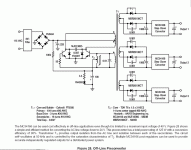
attached is a GIF of the off-line switcher using the On-Semi MC34166 chip and MJE13005 transistors -- with the transformer information clearly laid out -- the MC34166 is a 3 amp 40V max switcher -- the idea is to use the MJE13005s as a self-starting multivibrator, then use the controller chips on the secondaries in their various configurations. On-Semi has taken the time to provide PCB patterns for the stepdown converters on the product PDF:
http://www.onsemi.com/pub/Collateral/MC34166-D.PDF
http://www.onsemi.com/pub/Collateral/MC34166-D.PDF
Attachments
You can drive as much MOSFETs as you want from a single SG3525 as long as the maximum drive current specified for that IC is not exceeded [+-500mA I think]
Gate drive current is limited by gate resistor value. The most conservative way to calculate maximum gate drive current is to divide 12V by the equivalent resistance of the amount of gate resistors connected in paralell to each output, but looking at the waveforms with an oscilloscope reveals that actual peak current drawn is usually 2 to 4 times lower than expected due to IC rise and fall times
Obviously, MOSFET rise and fall times are highly depend on the magnitude of the gate drive current. Increasing the amount of MOSFETS driven from a single IC also requires increasing the value of gate resistors to keep the IC working below its drive capability, so adding more devices without buffering the output of the IC means slower switching
There is always a compromise buy you will need to build a prototype to evaluate it
10x for the reply .... it`s my first smps ... i have had a few attemps but failed before
i just finished my experimental smps it`s point to point uses sg3525 and 2xirfz48n .
the idle curent is about 250mA is that good ?? the mos-fet`s are cold with no load and no heatsinks !
i just finished my experimental smps it`s point to point uses sg3525 and 2xirfz48n .
the idle curent is about 250mA is that good ?? the mos-fet`s are cold with no load and no heatsinks !
B.I.G said:10x for the reply .... it`s my first smps ... i have had a few attemps but failed before
i just finished my experimental smps it`s point to point uses sg3525 and 2xirfz48n .
the idle curent is about 250mA is that good ?? the mos-fet`s are cold with no load and no heatsinks !
groannnnnn....
")
don't use P2P for SMPS -- things which seem small in the 3D world are enormous when you consider that large currents switching in very small periods of time face enormous impedances. layout, groundplane, nanohenries of inductance are all critical, even with low switching speeds. it's the transition which kills.
- Status
- This old topic is closed. If you want to reopen this topic, contact a moderator using the "Report Post" button.
- Home
- General Interest
- Car Audio
- toroid for car amp smps