G'day Tony.
I have been having some fun with my scope and am starting to learn what means what.
Input Cable - I have disconnected one of the input leads and connected the scope to the output. With the 300mm long lead held away from the amp I seem to have around 2mV of general noise.
As I move the lead closer to the transformers I get a more defined 100Hz trace of about 2 - 5mV.
When I place the input cable right next to the mains input area it peaks at about
15 - 20mV and starts to show the 50Hz over the 100Hz.
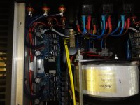
I have taken this photo of the amp's star earth to clarify the layout.
-The White cables running under the boards is the earth from each module.
-The yellow cables are from the separator plates between each taroidal.
-You can see the safety earth from the main socket running yellow wires into the right hand back of the earth block.
- The input and output terminals are isolated from the back plate with plastic spacers that run through the hole.
Should I start removing non critical elements from the star earth structure and see what happens?? Of course not the PCB earth points??
Cheers
Dean
I have been having some fun with my scope and am starting to learn what means what.
Input Cable - I have disconnected one of the input leads and connected the scope to the output. With the 300mm long lead held away from the amp I seem to have around 2mV of general noise.
As I move the lead closer to the transformers I get a more defined 100Hz trace of about 2 - 5mV.
When I place the input cable right next to the mains input area it peaks at about
15 - 20mV and starts to show the 50Hz over the 100Hz.
I have taken this photo of the amp's star earth to clarify the layout.
-The White cables running under the boards is the earth from each module.
-The yellow cables are from the separator plates between each taroidal.
-You can see the safety earth from the main socket running yellow wires into the right hand back of the earth block.
- The input and output terminals are isolated from the back plate with plastic spacers that run through the hole.
Should I start removing non critical elements from the star earth structure and see what happens?? Of course not the PCB earth points??
Cheers
Dean
Attachments
Ok, I will just keep talking to myself here, somebody else might find this info useful.
-I disconnected one of the two rectifier/amp modules from the transformer and just ran a single rectifier/amp.. No change.
- I ran earth leads from the two points on the PSU PCB back to the star earth block.. No change.
Hmmm.
Merry Christmas
-I disconnected one of the two rectifier/amp modules from the transformer and just ran a single rectifier/amp.. No change.
- I ran earth leads from the two points on the PSU PCB back to the star earth block.. No change.
Hmmm.
Merry Christmas
Hi Dean, I've been out with the family. Might not have a chance to think about it till after Christmas ") It looks like each amp module has it's own power-supply correct? and each has one rectifier per rail ie one winding per rectifier?
It looks like each amp module has it's own power-supply correct? and each has one rectifier per rail ie one winding per rectifier?
Merry Christmas!! I have to go wrap some presents
Tony.
It looks like each amp module has it's own power-supply correct? and each has one rectifier per rail ie one winding per rectifier? Merry Christmas!! I have to go wrap some presents
Tony.
Those spikes look like charging pulses through the rectifiers.
They could couple electrically through a common trace/wire, or magnetically across a pair of large area loops.
Did you do a trial assembly without a chassis? Can you easily dismantle the PSU and temporarily move it outside the chassis.
They could couple electrically through a common trace/wire, or magnetically across a pair of large area loops.
Did you do a trial assembly without a chassis? Can you easily dismantle the PSU and temporarily move it outside the chassis.
the charging circuit will show a 100Hz sawtooth waveform and a pulsed waveform.
These should be kept in a tight loop around the charging circuit only.
The audio side will be affected by the changing voltages across the smoothing caps. This will infiltrate into the audio signal processing.
Do your best to ensure that the audio side does not share are common wiring with the charging side. This is absolutely imperative, This is why one must NEVER locate the Main Audio Ground on the wire, cable, trace, plate between the smoothing caps.
Good to hear from you Andrew, I was hoping you would be around.
Hope your Christmas has gone well. Melbourne flooded today(along with my shed) so I cant work on the amp but I have a quick pic with a more complete one on the way.
In regards to your grounding observations, the only thing I can think of is that the AS4222's have a static shield around them with a lead-out wire that I have connected to the star-earth block, along with the amp ground leads. I also have an alloy plate between each transformer which also has a lead running to the star-earth block.
I guess I should try removing these from the earth block and look for changes on the scope, but I am not sure if this is what you are referring to.
To be honest I am not experienced enough to accurately interpret your advice in relation to what I have built.
Thanks for your patience all. I cant wait to resolve this issue and move onto some music but I am learning a lot and taking it slowly.
Cheers
Dean
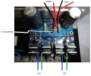
Correction: "To Ground Block" = Star Earth Block. There is only one large brass block that EVERYTHING goes to.
I have checked for shorts between panels and connectors... etc.
All 6 channels have the same amount of 'hum' with the same trace on the scope, a 100Hz 6-8mV squarish wave. As shown in a previous pic
Hope your Christmas has gone well. Melbourne flooded today(along with my shed) so I cant work on the amp but I have a quick pic with a more complete one on the way.
In regards to your grounding observations, the only thing I can think of is that the AS4222's have a static shield around them with a lead-out wire that I have connected to the star-earth block, along with the amp ground leads. I also have an alloy plate between each transformer which also has a lead running to the star-earth block.
I guess I should try removing these from the earth block and look for changes on the scope, but I am not sure if this is what you are referring to.
To be honest I am not experienced enough to accurately interpret your advice in relation to what I have built.
Thanks for your patience all. I cant wait to resolve this issue and move onto some music but I am learning a lot and taking it slowly.
Cheers
Dean
Correction: "To Ground Block" = Star Earth Block. There is only one large brass block that EVERYTHING goes to.
I have checked for shorts between panels and connectors... etc.
All 6 channels have the same amount of 'hum' with the same trace on the scope, a 100Hz 6-8mV squarish wave. As shown in a previous pic
Attachments
Last edited:
Hi Dean, what size are the filter caps on the amp board? From what I can see it is a very minimal design. I suspect 1000uF caps??
I know that my LM3886 had 100Hz spikes on the output (not as big as yours) and only had 1000uF / rail on the PS (though it also had local 100uF decoupling on the LM3886 pins).
Increasing the PS caps to 5700uF in total almost completely eliminated the 100Hz noise.
I'd say it's worth while trying to disconnect the alloy plates from the star earth block. I'm speculating here that rectifier pulses back through the transformer and the resulting EMI may be inducing current in the alloy plates which could be then polluting your earth.
Have you tried the scope measurements with 2, 4, and 6 channels running? Is there any difference?
Hope there wasn't too much damage from the flooding!! and not too big a cleanup.
Tony.
Ok, so I spent the last 6 hours digging out the shed after the flood so I could get to the workbench. The house is fine with no real damage but we have discovered were the drainage situation could be improved in a few places.
Amp testing time.... I am becoming more comfortable using the scope so this has been a good opportunity to learn something.
1. Single module running, 100Hz 6mV noise on scope and hum at speaker.
a) Add another psu/amp module = no change
b) Turn on all other modules = no change
c) Connect Alloy shield plates (between trany's) to star-earth = no change
d) Connect static shield from around trany's to star-earth = no change
e) Connect shielded wire from input to rca on back panel = no change
f) Drink a beer and scratch head = no change
I have been reading the other threads you posted Tony. I am looking at ordering some larger caps and testing the theory unless other suggestions are made.
I have to admit It will be a little disappointing to find out that the amp with the existing caps was prone to noise and have never heard mention of the possible issue on the AudioSector web site.
I know this is DIY but........
Cheers
Dean
Hi Dean, this post http://www.diyaudio.com/forums/powe...ding-challenge-please-help-7.html#post2519106 and the next one show the difference on my LM3886 with 1000uF / rail and 5700uF/rail on the powersupply.
Note that in general it is pretty noisy (in that the scope trace is thick), I don't have any rf filtering on the input, and I think it needs it. I don't think I'd worked out that I could put the scope into 2mV/div mode at that point
Good to hear the house isn't damaged, and nice to hear you are getting the hang of the scope. It took me a while too, and I'm sure I still have a lot to learn, but it is a very useful tool!
Tony.
Is that 6mVpp of noise on the scope?
Can you estimate what portion of that 6mVpp is HF noise and what is LF noise?
Can you measure that same noise with an AC DMM or voltmeter?
What does the voltmeter read?
Do any of the noise voltages change when you short and open the amp input?
Have you tried a dummy Rs load on the amp input?
Can you estimate what portion of that 6mVpp is HF noise and what is LF noise?
Can you measure that same noise with an AC DMM or voltmeter?
What does the voltmeter read?
Do any of the noise voltages change when you short and open the amp input?
Have you tried a dummy Rs load on the amp input?
.
I have to admit It will be a little disappointing to find out that the amp with the existing caps was prone to noise and have never heard mention of the possible issue on the AudioSector web site.
I know this is DIY but........
There's a simple way to check it: isolate one amp channel (which means disconnecting everything else except for one amp channel), ground the input and check if it hums. If it doesn't, the problem in your setup comes form grounding.
The amp will produce noise without input connected to the source or grounded.
Hi Dean and Peter,
Sorry for riding on your thread on this issue, I have similar hum issue with my 2 channels setup. I have 1 transformer with 2 secondary (2x 25VAC) feeding 2 x 3875 Chipamp modules with both having it's own PSU module.
Trans(1) -P1 feeding PSU1 of AMP1 and PSU2 of AMP2 on positive rail
Trans(1) -P2 feeding PSU1 of AMP1 and PSU2 of AMP2 on Negative rail
When I isolate one PSU-AMP module by disconnecting the power rails on one module, no hum, very quiet on the other module. This applies to both PSU-AMP module when I swap it so this shown the PSU-AMP module is working fine. Only when I connect both PSU-AMP to the same transformer then it hum. Please note that I have not connect the SC ground and no ground breaker yet, the whole thing is on a cutting board for modup.
I followed Peter's grouding method for each module, do I need to handle the start ground differently when connecting a single transformer to 2 PSU-AMP module? Any suggestion?
Thanks
Last edited:
Hey.
I first made my 6xLM4780 build with dual mono 12Ah battery banks, no-noise-at-all. Built a 2xLM3875 thingy with a regular trafo, really happy with it, no noise at all.
Decided my "chief" setup it took up too much space, replaced the battery banks with 4x300VA 2x24V trafo's. Now i have noise on all channels, so I will be going back to my dual battery banks, the battery banks will be built into a slightly ventilated wooden box and hidden behind my 305lTH, so not a big issue, as opposed to before when it was all out in the open.
Just saying I also have these problems.
I have tried everything to get rid of the hum, it seems impossible.
Edit: It seems like hum is worsening for each trafo i connect to the system, it is probably just feeding more potential noise into common. I have tried reversing the phase of each trafo i add, makes no difference.
Last edited:
OK, finally had enough time today to get the amp onto the test bench and disconnect everything but 1 channel. I then took an alligator lead and placed one end on the star earth block and the other on the outside of the rca connector.
I forgot to take a photo but the 100hz hum looks the same with the lead connected or not. So no change on that front.
Do you think its worth trying larger caps Peter (+others), say 4700uF and see what happens? If so, what brand would be best?
Cheers all. Dean
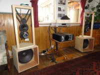
PS. I have had the amp running (with hum) and am having slow but great success with my miniDSP/OB rig. More bass than I have every had before from the 2 x 15's. In every other regard the AudioSector LM4780's have been operating flawlessly.
I forgot to take a photo but the 100hz hum looks the same with the lead connected or not. So no change on that front.
Do you think its worth trying larger caps Peter (+others), say 4700uF and see what happens? If so, what brand would be best?
Cheers all. Dean
PS. I have had the amp running (with hum) and am having slow but great success with my miniDSP/OB rig. More bass than I have every had before from the 2 x 15's. In every other regard the AudioSector LM4780's have been operating flawlessly.
Attachments
OK, finally had enough time today to get the amp onto the test bench and disconnect everything but 1 channel. I then took an alligator lead and placed one end on the star earth block and the other on the outside of the rca connector.
That does not ground the input, it needs to be connected to the "inside" of RCA connector.
If you are experiencing hum issues, larger cap will not help here.
- Status
- This old topic is closed. If you want to reopen this topic, contact a moderator using the "Report Post" button.
- Home
- More Vendors...
- Audio Sector
- 6 Channel Amp Wiring Advice