At an equilibrium, the forces along the tonearm must balance out. Similarly the torques about the horizontal pivot must balance.
Could you please advise accurate coordinates for all the relevant points in diagram 1?
I'd like to CAD something up and do a multibody physics simulation for you.
It's an ellipse, the circle is only a convenient compromise. That ellipse pops up in so many pivoting tangential geometries.
Yup, what he said.
If you extend each “tone arm” line to a point a couple of centimeters beyond the current points, the resulting curve will be magnified and the ellipse quite apparent. That’s especially true if you add more lines. The gaps that super10018 found in his drawing are the result of the difference between a circle and an ellipse.
At the stylus end, over at “90 degrees,” jonathon Carr posted an exhaustive data set which shows the stylus position and tracking error for birch/Thales arms relative to a Thales circle. The results are specific to particular tonearm and control arm lengths. One of the Reed 5A graphs shows it’s tangency is excellent, but not perfect because the dual arm is a birch/Thales design and as long as the control arm follows a circle, that slight intangency will be there.
Despite that, it’s magnitudes better than standard pivot arms and the difference is audible.
Could you please advise accurate coordinates for all the relevant points in diagram 1?
I'd like to CAD something up and do a multibody physics simulation for you.
Thanks for the generous offer. It is gratifying that I have stirred up some interest.
I don’t have access to such software anymore. I let my Mathematica licence expire.
Constant parameters:
Inner groove radius, a = 5.75
Outer groove radius, b = 14.605
Effective tonearm length at outer groove, L = 25
Total tonearm length l = sqrt(L^2 + b^2) = 28.954
Let r be the radial distance from the disc centre. The for the grooved area of the disc, 5.75 ≤ r ≤ 14.605
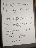
Let the cartesian coordinates of the stylus be (x(r), y(r)).
Let the cartesian coordinates of the tonearm rear be (X(r), Y(r)).
Attachments
Please correct me if my methodology is incorrect.
Jim
Hi Jim.
As 2wice and others have said, the rear path is not a circle, although a good fit can be achieved over the groove region. See my graph of post #151. The green path is the exact rear path.
Orthogonal to which plane? The one the tangent to groove force lies on?
In the horizontal plane containing the stylus, groove force and sliding bearing.
Also, what convinces you that a variable anti-skate is required?
My earlier calculations give
Skating torque = r F
where F is the stylus drag force. The literature is ambiguous about whether F decreases with r or is constant. In either case skating torque decreases with r.
Thanks for the generous offer. It is gratifying that I have stirred up some interest.
I don’t have access to such software anymore. I let my Mathematica licence expire.
Constant parameters:
Inner groove radius, a = 5.75
Outer groove radius, b = 14.605
Effective tonearm length at outer groove, L = 25
Total tonearm length l = sqrt(L^2 + b^2) = 28.954
Let r be the radial distance from the disc centre. The for the grooved area of the disc, 5.75 ≤ r ≤ 14.605
Let the cartesian coordinates of the stylus be (x(r), y(r)).
Let the cartesian coordinates of the tonearm rear be (X(r), Y(r)).
What is the fixed horizontal pivot (x,y) please?
What is the fixed horizontal pivot (x,y) please?
Both sets of coordinates (x(r), y(r)), and (X(r), Y(r)) are the cartesian coordinates with respect to the origin
(0, 0), where the sliding pivot is fixed. The variable r is however the distance from the platter centre (25, -14.605) in both cases, NOT the usual radial distance from the origin. The parametrisation works much better this way.
It often turns out that the choice of coordinates makes things much simpler. I suppose using the symbol "r" in this way could cause confusion, since it is not the usual radial distance from the origin. Just think of r like a standard parameter, say "t" in the parametric form of the unit circle, x(t) = cos(t), y(t) = sin(t)
To check that you have it correct, substitute r = b = 14.605 into the parametrisation and you should get (x(14.605), y(14.605)) = (25, 0), the cartesian coordinates of stylus location on the outer groove. Substituting r = 0, you should get (x(0), y(0)) = (L, -b) = (25, -14.605), the cartesian coordinates of the platter centre.
This parametrisation makes it easy to track the stylus path at each radial distance from the platter centre.
Hope this helps.

The point you indicate in #170 is not a fixed point. It is the reflection of the stylus coordinate in the Thales circle centre in #157. It is not physically attached to anything.
It varies with the stylus position. Just translate the stylus coordinates (x(r), y(r)) as follows: The point you indicate has coordinates (U(r), V(r)), where
(U(r), V(r)) = (x (r), y(r)) + 2((L/2,-b/2)-(x(r), y(r)))
= (L, -b) - (x(r), y(r)) = (25, -14.605) - (x(r), y(r))
for 5.75 ≤ r ≤ 14.605

If the point on the graph is not fixed, then what is this?
And where is that point on the graph?
You must have missed this from post #85.
I am seeking a passive solution that addresses the issue in more direct fashion.
So I went back to the main result, the tangential stylus path and the rear end path are known exactly.
Previously the rear end path was closely approximated by a unique circle and a strut enforced the rear circular path, to give a close approximation to a tangential stylus path. I will leave this approach for the meanwhile, to engage with exact tangential tracking.
Also from #152
At the tonearm rear, for modelling purposes the rear end path can be considered as a smooth wire (frictionless) followed by a threaded bead or small hoop, attached to the tonearm.
All my posts from #85 have been concerned with exact tangential tracking enforced by a precise curve following tonearm rear. A CNC machined cam surface is envisaged.
All my posts from #85 have been concerned with exact tangential tracking enforced by a precise curve following tonearm rear. A CNC machined cam surface is envisaged.
Understood, but until I have a clear understanding of how you are going to constrain the tonearm from running away with the tangent to groove force, I cannot simulate it for you, as it stands it will run straight into the spindle.
No, it is constrained by the groove.
Nope, it might be constrained radially to the spindle by the groove, but in front of the stylus is open runway, nearly perfectly in-line with the groove force.
It will run.
LOL, I just had a thought, the string test has an application in this scenario also.
Understood, but until I have a clear understanding of how you are going to constrain the tonearm from running away with the tangent to groove force, I cannot simulate it for you, as it stands it will run straight into the spindle.
I will work on a demonstration working model. Give me few days.
probably by adding all four (+1 tonearm) moving elements (wands) by their lengths and pivots ? I am clueless about effective mass maths/formulas. Naturally it will be higher than typical tonearm; needing best quality bearings.Also, how did they calculate the effective mass? It looks suspiciously like they are only listing the vertical effective mass because I'm having a devil of a time calculating the horizontal effective mass myself, I think it's dynamic due to the moving COM. I'm very keen on seeing a solution for that.
Regards
probably by adding all four (+1 tonearm) moving elements (wands) by their lengths and pivots ? I am clueless about effective mass maths/formulas. Naturally it will be higher than typical tonearm; needing best quality bearings.
Regards
Doing that does not account for the moving centre of mass because of the translating counterweight and the extension of the effective length.
Possible method would be to seize the vertical bearing at the start position.
Turn the tonearm horizontal, add a second, temporary counterweight to the horizontal pivot, balance the whole contraption and calculate the effective mass as normal. Maybe take half the amount as the effective weight or make provision for the removal of second CW from the equation.
No need to do this physically, should be able to model this.
That only gives you the effective mass at the first groove, have to do the whole thing again for the second groove.
This would only be for curiosity as I doubt it has much effect on the signal.
- Home
- Source & Line
- Analogue Source
- A tangential tracking pivoting tonearm