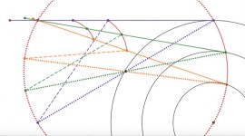
An animation showing the 25 cm tonearm motion (solid green line) with a cam at 20 cm. The dotted green line is the diameter of the Thales circle from the stylus to the dual point. The dashed green line is the normal vector at the cam.
Cam movie - YouTube
Cam movie - YouTube
My goal remains to discover whether perfect tangential tracking is achievable in the context of a passive pivoting tonearm mechanism. I have been refining the model based on geometric principles and elementary mechanics.
The itention is to allow no geometrical approximations in my modelling. The geometric accuracy will be purely determined by the precision of the numerical calculations. The inner recorded groove radius is only used in this model, as a stopping criterion for some calculations. There is no effect on the geometric alignment accuracy, and in principle the inner groove radius can be any value between zero and the standard outer groove radius. Similarly, provided it can reach to the innermost recorded groove, the physical length of the main beam will have no bearing on the geometric alignment. This can be illustrated by choosing a very short main beam as an example. This is not the case with approximate models, the accuracy usually dropping as the main beam length shortens and the inner groove radius decreases. The calculations based on this model do not appear to be more difficult than for approximate models.
Movie 1 shows the circular path for rear guide attachment and a short overall tonearm length. The rear guide circle can be a machined groove or rail followed by a rolling element which also supports a horizontal rotating bearing attached to the rear guide. A similar structure supports the main beam at the fixed location on the Thales circle. The guide and tonearm main beam are connected by a plain horizontal bearing.
The orange lines at the stylus end and rear guidance strut represent the stylus drag force vector and equal compensating anti-skating force vector (weight on a string). The geometry shows they generate equal and opposite torques about the Instantaneous Centre of Rotation (IC) of the tonearm main beam, which lies at the common intersection point on the Thales circle of the dashed lines.
I think the arm can be implemented. Please see the gif I did base on your model. I did a small modification and moved the center of the Thales circle out of the surface of the LP. Otherwise, in my opinion, it will cause unnecessary complexity.
There are three things I dislike or have concerns about.
1. The arm wand is about 300 mm. It makes me uncomfortable. I can't give you the reasons but it is just my feeling.
2. I don't know how efficient the slider can be. If the slider is highly efficient, why do you want to make a PT arm? Isn't linear arm even better?
3. One of the pivots is just above the cartridge.
However, these are just my personal opinions. If you are committed, I think it is worth trying it out.
.gif")
There are three things I dislike or have concerns about.
1. The arm wand is about 300 mm. It makes me uncomfortable. I can't give you the reasons but it is just my feeling.
2. I don't know how efficient the slider can be. If the slider is highly efficient, why do you want to make a PT arm? Isn't linear arm even better?
3. One of the pivots is just above the cartridge.
However, these are just my personal opinions. If you are committed, I think it is worth trying it out.
Last edited:
I think you have misread my animation. There is nothing attached to the red Thales circle apart from the fixed swivelling bearing just at the top left corner. Nothing but armtube overhangs the LP at any point. The physical components of the mechanism are shown in mauve, consisting of the circular guide track, rolling bearings, rear guide arm. I have uploaded a stripped back video below with only the Thales stylus path (red) retained.I did a small modification and moved the center of the Thales circle out of the surface of the LP. Otherwise, in my opinion, it will cause unnecessary complexity.
I have uploaded a version with a 50 mm shorter main beam. The main beam is 154.4mm. The guide arm is 1/2 this value. Nothing long by conventional standards.There are three things I dislike or have concerns about.
1. The arm wand is about 300 mm. It makes me uncomfortable. I can't give you the reasons but it is just my feeling.
The main tonearm pivot is a rolling bearing, not sliding. Rolling friction is orders of magnitude less than sliding friction.2. I don't know how efficient the slider can be. If the slider is highly efficient, why do you want to make a PT arm? Isn't linear arm even better?
Misreading again. See my new animations.3. One of the pivots is just above the cartridge.
Yes, I am going ahead ... slowly.However, these are just my personal opinions. If you are committed, I think it is worth trying it out.
View attachment 1004419
As it stands, the geometry makes the reaction forces straightforward to determine.
Same video as above with clutter removed.
Very short main beam
I think the arm can be implemented. Please see the gif I did base on your model. I did a small modification and moved the center of the Thales circle out of the surface of the LP. Otherwise, in my opinion, it will cause unnecessary complexity.
What you ended up with is similar to the THALES original model called the Original.
Not really. There is no pivoting headshell or ancillary tonearm beam.What you ended up with is similar to the THALES original model called the Original.
The Thales guide mechanism is neither coplanar or parallel to the horizontal principal geometry.
The issue is that for a stylus end that follows a Thales circle, any other point along the tonearm follows a non-circular path called a roulette. All attempts to approximate such paths by circular arcs lead to deviations from the Thales circle (non tangential positioning) at the stylus end.
A solution can be found by allowing the guide strut to follow an appropriate circular path, but it is not obvious and does require a precise description of motion of the attachment point (roulette). The guide mechanism could be attached at any point of the main beam which does not interfere with the LP, but the rear mount has an advantage regarding anti-skating considerations.
No problem. Gave me an opportunity to expand anyway. ;-)I was responding and referring to super10018/Jim's graphics, nothing to do with Bon's.
Bon,
Sorry, I misrepresented your model.
Here are my thoughts about your model(2nd one).
My concern about the slider is still valid. It doesn't matter if it is rolling or not, I haven't seen an effective mechanical horizontal bearing yet. In your model, you add a guide in the rear. If you can make a magnetic guide the same as Schroder LT's, it may work. However, it isn't easy to make for DIYers.
In fact, you may not need to make a slider. You may do something similar to THALES original model thanks to DD's comments.
In my opinion, a pivot bearing is a golden standard for all the bearings. This is why I insist to use pivot bearings for a PT arm. Other exotic bearings may not work as well as pivot bearings.
In any case, good luck with your build!
Jim
Last edited:
What a coincidence!What you ended up with is similar to the THALES original model called the Original.
Hello Bon,My goal remains to discover whether perfect tangential tracking is achievable in the context of a passive pivoting tonearm mechanism. I have been refining the model based on geometric principles and elementary mechanics.
The itention is to allow no geometrical approximations in my modelling. The geometric accuracy will be purely determined by the precision of the numerical calculations. The inner recorded groove radius is only used in this model, as a stopping criterion for some calculations. There is no effect on the geometric alignment accuracy, and in principle the inner groove radius can be any value between zero and the standard outer groove radius. Similarly, provided it can reach to the innermost recorded groove, the physical length of the main beam will have no bearing on the geometric alignment. This can be illustrated by choosing a very short main beam as an example. This is not the case with approximate models, the accuracy usually dropping as the main beam length shortens and the inner groove radius decreases. The calculations based on this model do not appear to be more difficult than for approximate models.
Movie 1 shows the circular path for rear guide attachment and a short overall tonearm length. The rear guide circle can be a machined groove or rail followed by a rolling element which also supports a horizontal rotating bearing attached to the rear guide. A similar structure supports the main beam at the fixed location on the Thales circle. The guide and tonearm main beam are connected by a plain horizontal bearing.
The orange lines at the stylus end and rear guidance strut represent the stylus drag force vector and equal compensating anti-skating force vector (weight on a string). The geometry shows they generate equal and opposite torques about the Instantaneous Centre of Rotation (IC) of the tonearm main beam, which lies at the common intersection point on the Thales circle of the dashed lines.
To make sure that you and I are on the same page:
Do you agree that your proposed tone arm is subject to the "inward force?
If you do, I may have a suggestion as to how to make said "inward force" work in your favor.
I have done that in my own pivoting tangentially tracking tone arm design.
Can I reproduce the geometry in your video in my own CAD program without using the exact same dimensions that you have used?
I other words, is the geometry scalable?
I may also have an idea for a low friction design for your slide through pivot.
In 1978, when I started to design tone arms, I came up with four different principles to achieve tangential tracking in a pivoting tone arm. One of them was the sliding/rolling pivot. I never went past a few sketches because I could not design a low friction way to do that. I hope that you are better at that than I was.
I think that pivoting tangentially tracking tone arms are superior to any other kind.
Sincerely,
Ralf
Hi Ralf,
 Hello Bon,
To make sure that you and I are on the same page:
Do you agree that your proposed tone arm is subject to the "inward force?
Can I reproduce the geometry in your video in my own CAD program without using the exact same dimensions that you have used?
I other words, is the geometry scalable?
I may also have an idea for a low friction design for your slide through pivot.
In 1978, when I started to design tone arms, I came up with four different principles to achieve tangential tracking in a pivoting tone arm. One of them was the sliding/rolling pivot. I never went past a few sketches because I could not design a low friction way to do that. I hope that you are better at that than I was.
I think that pivoting tangentially tracking tone arms are superior to any other kind.
Sincerely,
Ralf
Thanks for the offer to check my geometry in your CAD program. I don't think it is scalable given the nature of the trig and coordinate geometry gymnastics involved, but I will be glad for you to confirm (or otherwise!) the tangential tracking performance for the three sets of data from the jpg's attached. The only variable parameter is the distance L of the sliding pivot from the outer tangential groove. I have supplied the cases L = 10 cm, L =15cm, L=20 cm.
The outer groove diameter is 14.605 cm, inner groove diameter is 5.75 cm. The centre of the guide circle is marked between the outer and inner groove in each case.
If the tangency checks out, I can supply you with the data for your choices of L .
I don't want to get ahead of myself and accept your other generous offers with construction details until you are satisfied with the geometry. There certainly is a skating torque about the instantaneous centre of rotation of the main beam.
My motivation for this project is to experience LP replay closer to what the cutting lathe produces. Can I notice a difference? I want to know.
Regards
Bon
I meant radiusHi Ralf,
The outer groove diameter is 14.605 cm, inner groove diameter is 5.75 cm.
Plenty of devils to banish. There are two rolling pivots to solve for starters. The other pivots are conventional but need to be capable of exceptional performance.For pt arms, the devil is in the implements.
I am looking forward to your implementation.
One way to check the tangency in a CAD simulation is to dynamically check the Pythagoras theorem for a right angle triangle in the Thales circle as the CAD program scrolls from outer groove radius to inner groove radius (or even the platter centre).Hi Ralf,
If the tangency checks out,
The triangle has vertices; platter centre, stylus, sliding pivot. This would be an independent check of my graphing software, where I would effectively only be checking the trig library functions. In any case, I get a difference in a^2+b^2-c^2 of the order 10^(-15). We can call it zero, I think.
The tangential geometry alignment works when the guide strut attachment point is anywhere along the main beam, not only at the rear. The rear attachment is initially proposed to keep the horizontal bearing as far from the stylus as possible. There is then the potential for any induced bearing noise to be damped before it reaches the cartridge.
OTOH, moving the guide strut attachment to, say the main beam mid-point, results in a more compact tonearm.
Tangency at the stylus is unaffected.
The intriguing situation arises of leaving both guide arms in place. The result resembles the Birch style tonearms discussed in the other threads, but is more complex due to rolling pivots. Also a second guide adds nothing to the operation apart from increased friction and moving mass.
If a highly efficient rail guiding mechanism does exist, you may not need the additional link. Please see the green line.

- Home
- Source & Line
- Analogue Source
- A tangential tracking pivoting tonearm