A tangential tracking pivoting tonearm #20
What doesn’t seem to be taken into account is that there is always a rear tonearm reaction force to any strut, wire, cam or whatever the tonearm is attached to, for the purpose of enforcing tangency. With the assumption that ideally such attachments are frictionless, the tonearm experiences a rear force reaction that is orthogonal to the curve. This force has a component along the tonearm which opposes the frictional drag force. The larger the stylus/groove drag, the larger the opposing reaction component. I showed the vector orientation in Diagram 2 of post #152 . The tonearm component and the orthogonal component which comprise the force parallelogram, are shown. The orthogonal component determines the skating torque induced by the stylus/groove drag force and rear curve contact.
In my latest video below, I have replaced the rear strut with a cam machined to the profile of the rear curve. The cam material is HDPE, which is quite low friction but certainly there are much better machinable low friction engineering plastics. All of the sliding components are lubricated with Teflon (PTFE) lubricant. The cam slider is a smooth stainless steel cylinder nut that fits the cam profile with a gap of better than 0.5 mm. This is just for demonstration purposes.
In the video, it can be seen that when the tonearm is placed in a tangential position on a rotating acrylic disc, it remains tangential and stable. It does not run towards the spindle. The extended stylus end bolt points towards the spindle in all situations.
Since the drag friction increases with down force, I have massively loaded up the stylus end with additional M10 nuts. The increased friction drag is very audible but the tangency remains undisturbed. The rear reaction ramps up to counter the increased drag. There is no tendency to run at the spindle.
As previously, if the tonearm is slightly off tangential, it skates inwards or outwards to assume the tangency position. I am speculating that even though a tangential tracking tonearm may have non-zero sidethrust, the amount of sidethrust is very much less than that experienced by a fixed pivoted tonearm with overhang.
I have no first hand experience with passive parallel tracking tonearms, but it must be the case that there is an unavoidable sidethrust or the stylus would not follow the spiral groove.
Tonearm rear cam - YouTube
At an equilibrium, the forces along the tonearm must balance out. Similarly the torques about the horizontal pivot must balance... Then the component along the tone arm (blue) must equal and oppose the frictional drag
Understood, but until I have a clear understanding of how you are going to constrain the tonearm from running away with the tangent to groove force,
... as it stands it will run straight into the spindle.
It will run.
What doesn’t seem to be taken into account is that there is always a rear tonearm reaction force to any strut, wire, cam or whatever the tonearm is attached to, for the purpose of enforcing tangency. With the assumption that ideally such attachments are frictionless, the tonearm experiences a rear force reaction that is orthogonal to the curve. This force has a component along the tonearm which opposes the frictional drag force. The larger the stylus/groove drag, the larger the opposing reaction component. I showed the vector orientation in Diagram 2 of post #152 . The tonearm component and the orthogonal component which comprise the force parallelogram, are shown. The orthogonal component determines the skating torque induced by the stylus/groove drag force and rear curve contact.
In my latest video below, I have replaced the rear strut with a cam machined to the profile of the rear curve. The cam material is HDPE, which is quite low friction but certainly there are much better machinable low friction engineering plastics. All of the sliding components are lubricated with Teflon (PTFE) lubricant. The cam slider is a smooth stainless steel cylinder nut that fits the cam profile with a gap of better than 0.5 mm. This is just for demonstration purposes.
In the video, it can be seen that when the tonearm is placed in a tangential position on a rotating acrylic disc, it remains tangential and stable. It does not run towards the spindle. The extended stylus end bolt points towards the spindle in all situations.
Since the drag friction increases with down force, I have massively loaded up the stylus end with additional M10 nuts. The increased friction drag is very audible but the tangency remains undisturbed. The rear reaction ramps up to counter the increased drag. There is no tendency to run at the spindle.
As previously, if the tonearm is slightly off tangential, it skates inwards or outwards to assume the tangency position. I am speculating that even though a tangential tracking tonearm may have non-zero sidethrust, the amount of sidethrust is very much less than that experienced by a fixed pivoted tonearm with overhang.
I have no first hand experience with passive parallel tracking tonearms, but it must be the case that there is an unavoidable sidethrust or the stylus would not follow the spiral groove.
Tonearm rear cam - YouTube
I still have some doubts. If the tonearm is sligthly off tangential, it can't skate inwards or outwards on a grooved disc. The stylus tip can follow only the groove, and there should be a force vector component pushing or pulling the whole arm assembly so that the stylus tip end of the tonearm moves along the groove until it becomes tangential. That force should be perfectly balanced at the tangential position, even if the stylus is dragged by the friction force. I think a better demonstration would be to place the simulated stylus onto a groove at, say 70 mm, 100 mm, 140 mm radius, and see if the arm takes up tangential position within that certain groove by itself. You can push the stylus to and fro from the tangential position (within the groove) and see if it returns to its original position. Also is there any oscillation? Well, there are skating forces, but this is irrelevant for achieving tangency. It is not the skating force that moves the arm to tangential position. You can deal with that force component later on.As previously, if the tonearm is slightly off tangential, it skates inwards or outwards to assume the tangency position.
Also, the surface friction from the little roller in the front is not enough to overcome the stiction in your linear bearing/CAM mechanism.
If you can manually move the tonearm forward over the tangent line, then a "frictionless" tonearm will run.
If you can manually move the tonearm forward over the tangent line, then a "frictionless" tonearm will run.
Also, the surface friction from the little roller in the front is not enough to overcome the stiction in your linear bearing/CAM mechanism.
I already raised this issue back in post #32, and got a lecture on the rolling frictional drag of automobile tires in post #39. Didn’t you take notes?
Ray K
Also, the surface friction from the little roller in the front is not enough to overcome the stiction in your linear bearing/CAM mechanism.
Did you not watch the second half of the video? To check your theory, I upped the front end load to 100 gm. Together with the extended tonearm mass, the downforce was 150 gm. Nothing changed except the screeching from the frictional drag on the disc was intolerable. You must know that friction is roughly proportional to vertical load so it is way over the value to overcome any stiction. Even without the increased load, any stiction was insufficient to prevent the tangential seeking motion.
If you can manually move the tonearm forward over the tangent line, then a "frictionless" tonearm will run.
It is clear that mathematics, mechanics and videos are not sufficient to challenge your view.
It is clear that mathematics, mechanics and videos are not sufficient to challenge your view.
Here is something challenging for you.
Once the tonearm is steady on your rotating platter. Push the headshell towards the spindle, the rear does not translate on the curve (as observed in your video), but the tonearm tends to tangent equilibrium. This shows the 1st horizontal pivot.
The second horizontal pivot appears to be hard for you to see.
The new cam follower you have made has a point that is constrained to an arc of an ellipse, the centre of which is your second horizontal pivot. You can easily test this with a pin on the ellipse centre, rubber band to the cam follower and a string (dear deity) instead of a tonearm, pull the string in whatever direction you desire (if the cam follower has a race on the complete ellipse.). The rubber band and string will tend to collinear. Congratulation! You have just discovered your effective length.
You know what happens to a tonearm with 2 horizontal pivots? ...
I'm sure you are delighted to have just read my last contribution here, now that it has devolved into insult.
I still have some doubts. If the tonearm is sligthly off tangential, it can't skate inwards or outwards on a grooved disc. The stylus tip can follow only the groove, and there should be a force vector component pushing or pulling the whole arm assembly so that the stylus tip end of the tonearm moves along the groove until it becomes tangential. That force should be perfectly balanced at the tangential position, even if the stylus is dragged by the friction force. I think a better demonstration would be to place the simulated stylus onto a groove at, say 70 mm, 100 mm, 140 mm radius, and see if the arm takes up tangential position within that certain groove by itself. You can push the stylus to and fro from the tangential position (within the groove) and see if it returns to its original position. Also is there any oscillation? Well, there are skating forces, but this is irrelevant for achieving tangency. It is not the skating force that moves the arm to tangential position. You can deal with that force component later on.
Hi lcsaszar.
You made some good points so I spent a while investigating the grooved disc operation.
The tonearm cannot skate in the groove if all components function as intended. Of course there has to be clearance in a practical tonearm. I looked at the situation where a conical stylus rests in a locked circular groove, but is displaced an infinitesimal amount along the groove, either forward or backward of the Thales circle. Because the stylus shape is assumed conical, stylus friction coefficient will not change with horizontal rotation relative to the groove.
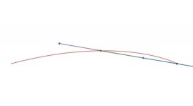
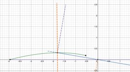
The friction drag is tangential to the groove and will have an outward component behind the Thales circle and an inward component in front of the Thales circle. Diagram 1 shows an exaggerated graphic with the tonearm at 3 different positions, green = tangential, blue = advanced, mauve = retarded. The angles are unrealistically large for clarity. In practice I would expect the distance between the three stylus positions to < 1 mm, possibly much less.
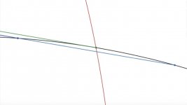
In Diagram 2, the view shows a more distant view, with the tonearm positions appearing co-linear, even with the excessive stylus displacements from tangential.
Diagram 3 shows an expanded view of the stylus end, and Diagram 4, an expanded view of the rear end.
Noteworthy is the incredibly close alignment of the rear end tonearm angle, even with the relatively massive stylus displacement from tangency. This is relevant because, with this geometry the rear reaction force vector shows minimal change due to stylus displacement. This means that the variation in the stylus drag angle to the tonearm will be the most significant change to tonearm tangential equilibrium.
The direction of the changed stylus drag force is consistent with the skating observations from the smooth acrylic disc.
It would be interesting to show a dynamic plot of the stylus position when starting from an off tangential position. On a smooth disc, the model does not show any overshoot, but I don’t have any result for the behaviour in a groove.
Attachments

I am speculating that even though a tangential tracking tonearm may have non-zero sidethrust, the amount of sidethrust is very much less than that experienced by a fixed pivoted tonearm with overhang.
Tonearm rear cam - YouTube
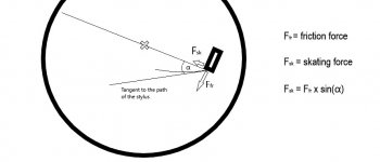
Here is a generalized equation for skating force, which is independent of the realization of the tonearm. Since the radius of the Thales circle is smaller than the effective length of a fixed pivoted tonearm, alpha is greater on every point and so is the skating force.
Attachments
In the case of a linear tracking tonearm with zero overhand the cartridge is not quite tangential to the groove, or else for every turn the groove must be on top of the preceding one. But if a cartridge is truely tangential to the record groove and has no over- or under-hang, where does any vector of non-tangential force on the stylus/cartridge come from?
Last edited:
In the case of a linear tracking tonearm with zero overhand the cartridge is not quite tangential to the groove, or else for every turn the groove must be on top of the preceding one. But if a cartridge is truely tangential to the record groove and has no over- or under-hang, where does any vector of non-tangential force on the stylus/cartridge come from?
I will assume that by linear tracking you mean tangential tracking. I can only speak for the tonearm geometry suggested here. The stylus/groove tangential drag induces a reaction at the rear curve (cam, track, etc) which has a component orthogonal to the tonearm, that produces a skating torque.
Where does the orthogonal component of force come from? how can it be generated without a non-zero offset?The stylus/groove tangential drag induces a reaction at the rear curve (cam, track, etc) which has a component orthogonal to the tonearm, that produces a skating torque.
I discussed this in posts #147, #152, 2nd diagram.Where does the orthogonal component of force come from? how can it be generated without a non-zero offset?
Help me here - the skating force is generated by the action of the cam mechanism that adjusts the pivot position, and therefore acts from the pivot end of the tonearm?I discussed this in posts #147, #152, 2nd diagram.
From # 152 diagram 2 (see below). The stylus drag force is towards the right along the tonearm (solid blue line). The rear contact force reaction with a smooth cam (green curve) is always orthogonal to the cam (dashed orange line). This has a component along the tonearm towards the rear (dashed blue line) and a component orthogonal to the tonearm (dashed mauve line). This last component is what supplies a clockwise torque about the horizontal pivot (0,0) experienced as inward skating force at the stylus.Help me here - the skating force is generated by the action of the cam mechanism that adjusts the pivot position, and therefore acts from the pivot end of the tonearm?
Attachments
A tangential tracking pivoting tonearm #21
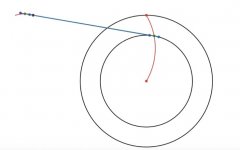
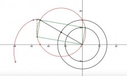
There is an interesting property of the proposed tangential tracking pivoting tonearm. In mathematics and physics, especially geometry and mechanics, there are principles that are bound together, which are called DUAL principles. Consequences that follow from applying one principle will inevitably enforce consequences from its dual principle. In geometry, the dual to the principle of TANGENCY, is ORTHOGONALITY. This is nicely illustrated when examining the tangency at the stylus end of the tonearm. There are consequences for orthogonality at the tonearm rear.
As I argued in #152, #195 , the skating force for tangential tracking is induced by a component of the rear reaction force. The tonearm rear reaction force is orthogonal to the rear path, for frictionless contact. The vector direction of this reaction is determined by the ”dual part” of the Thales circle (dotted red semicircle below).
For each stylus position on the Thales circle, the dual position diametrically opposite on the Thales circle, determines one end of the corresponding normal vector to the rear path. The other end is known on the rear path, corresponding to the stylus position.
in diagram 2, I have shown an expanded view of the tonearm rear, indicating the positions corresponding to outer groove, centre groove, spindle, the normal vector at the centre groove (green dashed), and three rear tangents at the outer, centre and spindle stylus positions.
I have shown the complete rear path for stylus on the Thales semi-circle, to emphasise that it is not a circle or ellipse.
Attachments

A tangential tracking pivoting tonearm #22
After considerations inspired from reading the other tangential tracking thread, I realised that the guide cam can be positioned in front of the horizontal sliding pivot with essentially no change to the operation. In fact, it has operational advantages.
1. The cam will occupy otherwise vacant real estate between the horizontal pivot and the platter, making for a more compact arrangement.
2. It will allow more space between the horizontal pivot and cam mechanism, to avoid physical interference.
3. It will declutter the rear of the tonearm which needs to accomodate a counterweight.
4. It allows more choice in the location of the cam along the tonearm. There may be an optimum position.
5. It will reduce the amplification effect of tolerance in the cam position at the stylus.
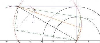
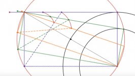
I have shown below, the geometric result of relocating the cam from the tonearm rear to a position 5 cm in front of the horizontal sliding pivot. That is, the cam is 20 cm from the stylus end of the 25 cm effective length tonearm. All of the essential geometric information is captured in the diagrams. I have left in place the positions for the rear positioned cam for comparison. The solid green line indicates the mid-groove tonearm position, with associated forward stylus/groove drag (dashed green), which induces an orthogonal force reaction at the cam (green dashed), which has a component along the tonearm (orange dashed) towards the rear, resisting the stylus/groove friction drag, and a component orthogonal to the tonearm (mauve dashed) creating inward skating torque. The duality principle (#196) relating the stylus tangency to the cam orthogonal reaction, is naturally preserved for all cam locations along the tonearm.
I emphasise that all of the graphics are based on exact calculation of the stylus and cam paths for tangential tracking. The accuracy is limited only by the precision of the graphical calculator software, which so far has had no problems coping.
Next step is to modify the working model and check out the operation. I am continually looking at lowering friction in the bearings to align the working model properties with the assumptions of the mathematical model.
After considerations inspired from reading the other tangential tracking thread, I realised that the guide cam can be positioned in front of the horizontal sliding pivot with essentially no change to the operation. In fact, it has operational advantages.
1. The cam will occupy otherwise vacant real estate between the horizontal pivot and the platter, making for a more compact arrangement.
2. It will allow more space between the horizontal pivot and cam mechanism, to avoid physical interference.
3. It will declutter the rear of the tonearm which needs to accomodate a counterweight.
4. It allows more choice in the location of the cam along the tonearm. There may be an optimum position.
5. It will reduce the amplification effect of tolerance in the cam position at the stylus.
I have shown below, the geometric result of relocating the cam from the tonearm rear to a position 5 cm in front of the horizontal sliding pivot. That is, the cam is 20 cm from the stylus end of the 25 cm effective length tonearm. All of the essential geometric information is captured in the diagrams. I have left in place the positions for the rear positioned cam for comparison. The solid green line indicates the mid-groove tonearm position, with associated forward stylus/groove drag (dashed green), which induces an orthogonal force reaction at the cam (green dashed), which has a component along the tonearm (orange dashed) towards the rear, resisting the stylus/groove friction drag, and a component orthogonal to the tonearm (mauve dashed) creating inward skating torque. The duality principle (#196) relating the stylus tangency to the cam orthogonal reaction, is naturally preserved for all cam locations along the tonearm.
I emphasise that all of the graphics are based on exact calculation of the stylus and cam paths for tangential tracking. The accuracy is limited only by the precision of the graphical calculator software, which so far has had no problems coping.
Next step is to modify the working model and check out the operation. I am continually looking at lowering friction in the bearings to align the working model properties with the assumptions of the mathematical model.
Attachments
A tangential tracking pivoting tonearm #23
Having realised that the tangential stylus path can be enforced by a cam positioned anywhere along the tonearm, I have produced animations showing the cam path for any choice of location from the horizontal pivot right up to the stylus. Of course locations where the cam path overlaps with the platter, seem pointless, but I recall the Townsend Excalibur tonearm damping trough that extended over the LP area. The cam surface would do something similar. Not very appealing but not impossible!
Interestingly, the Thales circle is one of the cam paths (the only one that is a circle), which makes sense if the cartridge is forced to follow the Thales circle and the tonearm only provides horizontal rotation that aligns the cartridge tangentially to the groove. This could be thought of as a parallel tracker with a curved track actually on the Thales circle. I am not seriously promoting any of these scenarios but just pointing out they are not ruled out.
With regard to the question of where to position the cam along the tonearm, the geometry might indicate that the rearward tonearm reaction force component is greater the closer the cam is to the stylus, and the smaller the skating torque. I am not sure overall whether this is a good or bad thing.
Tangential tonearm cams - YouTube
Tangential cams - YouTube
With regard to the question of where to position the cam along the tonearm, the geometry might indicate that the rearward tonearm reaction force component is greater the closer the cam is to the stylus, and the smaller the skating torque. I am not sure overall whether this is a good or bad thing.
The skating force at the stylus remains the same in either case.
It might be interesting to see where this comes from. It is not obvious. The geometry helps to understand.The skating force at the stylus remains the same in either case.
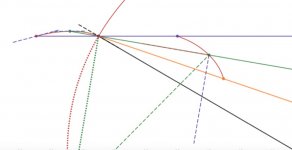
In the first case, for a 25 cm tonearm with cam located 20 cm from the stylus, the paths are as shown in Diagram 1 for stylus on the Thales circle at outer, mid, inner grooves. The acute angle (beta) between the tonearm (solid line) and normal (dashed line) at the cam, is decreasing as the tonearm moves inwards. This means that the force component orthogonal to the tonearm that is responsible for skating torque, decreases towards the spindle. However the distance of the cam from the horizontal pivot, increases as the tonearm moves inwards.
The same situation arises if the cam be positioned closer to the stylus, say 15 cm distance, as in Diagram 2. The distance to the horizontal pivot is initially greater than in Diagram 1 and further increases, hence the inwards skating torque about the horizontal pivot, increases towards the inner groove. However, the angle beta is more acute the closer the cam is located to the stylus, which decreases the cam reaction skating force compared to Diagram 1 and hence skating torque.
In any event, the skating torque is independent of the cam position.
Attachments

- Home
- Source & Line
- Analogue Source
- A tangential tracking pivoting tonearm