Birch Two pivot arm :
If we see it as very long headshell with bend (varying Offset) near pivot it seems it will skate.
addition : But with string test, since we dont know the force at which we pull the string is same as real world and friction at moving pivot it will be little difficult to judge. skating force may be very little I guess.
Last edited:
I changed my plan and am going to build a clone of Reed 5A because if I build a Birch two-pivot arm, it must be a non-working arm. A pure Birch two-pivot arm lacks a mechanism to ensure correct geometry. A non-working arm may act slightly different from a working version although a non-working version is much simpler to build. However, as far as skating, I believe there is no difference between a non-working Birch two-pivot arm and a working clone of Reed 5A. A non-working arm may leave room for speculations. In order to eliminate all the speculations, I will build a working version as much as I can.
Again, I expect the clone of Reed 5A doesn't skate.
Again, I expect the clone of Reed 5A doesn't skate.
Last edited:
loooong headshell
That's very perceptive of you to use such analogy, that is, a dual pivot arm can be seen as an arm with a very long headshell with a pivot. Using the Reed 5A drawing below taken from their video as example, since the main pivot (1P2), the one holding majority of the mass, and the "bend" (1B1, 1B2, 1B3) are both closer to the virtual Thales locus point (P3) and it will skate less than a conventional single pivot arm where the bend is at the headshell and much farther away from the locus (P3). Needless to say, the theoretical ideal skate-free tonearm is to have the main pivot and the bend (or no bend at all) located at the same locus point (P3). The reason we need linkage articulation is that we do not have an armwand that can change its length between two points.

Very good idea so we can all reference back to the Reed 5A drawing above for future discussion. You can even create a separate forum thread for it. (My apology to Bon again for hawking the space.)
The Reed 5A webpage does mention skating briefly: "Comparing to regular pivot tonearms, Reed 5A does not require antiskating and has much less absolute tracking error."
"Does not require" is not the same as no skating force at all. Nevertheless, your clone will verify their claim.
Birch Two pivot arm: If we see it as very long headshell with bend (varying Offset) near pivot it seems it will skate.
That's very perceptive of you to use such analogy, that is, a dual pivot arm can be seen as an arm with a very long headshell with a pivot. Using the Reed 5A drawing below taken from their video as example, since the main pivot (1P2), the one holding majority of the mass, and the "bend" (1B1, 1B2, 1B3) are both closer to the virtual Thales locus point (P3) and it will skate less than a conventional single pivot arm where the bend is at the headshell and much farther away from the locus (P3). Needless to say, the theoretical ideal skate-free tonearm is to have the main pivot and the bend (or no bend at all) located at the same locus point (P3). The reason we need linkage articulation is that we do not have an armwand that can change its length between two points.
I changed my plan and am going to build a clone of Reed 5A
Very good idea so we can all reference back to the Reed 5A drawing above for future discussion. You can even create a separate forum thread for it. (My apology to Bon again for hawking the space.)
The Reed 5A webpage does mention skating briefly: "Comparing to regular pivot tonearms, Reed 5A does not require antiskating and has much less absolute tracking error."
"Does not require" is not the same as no skating force at all. Nevertheless, your clone will verify their claim.
another thought that came to my mind but not 100% sure is, if tonearms like reed has multiple horizontal pivots/bearings the friction (Compared to typical tonearm) will overbear the already reduced skating force and results we get needs to be evaluated.
So we need to compare/measure (ratio ?) Typical tonearm friction and skating force <-to-> tangential tracking pivot arms friction and skating force.
So we need to compare/measure (ratio ?) Typical tonearm friction and skating force <-to-> tangential tracking pivot arms friction and skating force.
So we need to compare/measure (ratio ?) Typical tonearm friction and skating force <-to-> tangential tracking pivot arms friction and skating force.
Would be nice if they quoted the minimum starting torque as well as the cart compliance. Their site is not very clear on that.
Also, how did they calculate the effective mass? It looks suspiciously like they are only listing the vertical effective mass because I'm having a devil of a time calculating the horizontal effective mass myself, I think it's dynamic due to the moving COM. I'm very keen on seeing a solution for that.
A tangential tracking pivoting tonearm #16
It is more useful to determine the stylus skating torque with respect the horizontal pivot, rather than the skating force at the headshell. It is this torque that needs to be countered by the antiskating counter torque.
I considered it interesting to derive the skating torque formula for this geometry, as it is not clear if there is any departure from the known results for other tonearm geometries. I ask for your indulgence for what follows.
A nice formula appears for this geometry, that the skating torque is proportional to the radial distance multipled by the stylus friction force. This is as far as we can go, because the stylus friction force depends on a number of variables such as:
VTF,
Rotation speed,
Stylus profile,
Groove modulation,
Vinyl composition
It is clear that antiskate has to be a big compromise and the requirement will be different for each disc and cartridge. Perfect antiskating counter torque is an unattainable goal. Nevertheless I believe it is worthwhile to find a good approximation.
The attached diagrams can provide a justification for the skating torque formula mentioned above for those concerned with proof. The principles are as follows:
1. Assuming a frictionless cam guide at the tonearm rear, the force reaction is always normal to the rear path.
2. The normal reaction has a component along the tonearm determined by the acute angle beta between the normal and the tonearm. This component along the tonearm is exactly countered by the frictional drag by the stylus
3. The normal reaction has a component orthogonal to the tonearm which produces a torque about the horizontal pivot exactly counter to the stylus skating torque.
The diagrams show the geometry for the stylus at the mid-point radius. The right angled triangle mostly in the 3rd quadrant has side in the direction of the normal reaction, the normal to the tonearm, the tonearm rear. The angle at the pivot is 90 degrees, the angle between the tonearm rear and the normal is beta. The side opposite beta has the same length as the radius at the stylus. A straightforward trigonometric argument together with the principles 1-3 will lead to the conclusion. I don’t want the maths to be a distraction. I am certain there are many who will find the conclusion reasonable based on experience, geometric intuition etc.
Attachments
A nice formula appears for this geometry, that the skating torque is proportional to the radial distance multipled by the stylus friction force.
Can you show the maths please? All you have to do is add counter torque to the fixed horizontal pivot and skating goes poof. (Zero product property).
Can you show the maths please? All you have to do is add counter torque to the fixed horizontal pivot and skating goes poof. (Zero product property).
I am intrigued with what you guys are doing here! - you may also see that i muck around with a radial LTA on the other thread........
Pivots, friction, resistance are all interesting to me.
I suspect matching a torque with a counter would be easy in constant motion and very difficult in start stop.
On the RTA, IMHO the rolling resistance is little problem, its the starting resistance in the start stop world of eccentricity that poses a very variable load, and hence the quest to reduce this to zero or acceptably low.
I see the same likelihood here, eccentricity will be the stumbling block more than continuous motion across the disc.
Very interesting though!
M
A tangential tracking pivoting tonearm #17
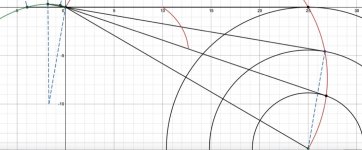
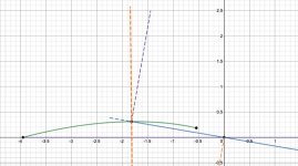
I have previously commented that the tonearm can be described purely geometrically, and here I am making the geometric construction explicit.
In my next post, I will explain my description of the skating torque, as requested by 2wice. The comments below refer to the attached diagram.
1. Draw LP circle radius 14.605 cm (outer groove) and mark the centre.
2. Draw a horizontal tangent from the top towards the left, sufficiently long (not crucial yet)
3. Mark off with a compass, from the circle tangent point, a distance along the tangent the chosen effective length of the tonearm at the outer groove position.(stylus to pivot)
4. Draw a line from this pivot point to the circle centre. This line is the Thales circle diameter. Its length is the total tonearm length, from stylus to rear end.
5. Bisect the line above and using the bisection as a centre and draw the (Thales) circle joining LP circle centre and the pivot point (#3).This gives the stylus path (red) for tangential tracking.
6. With a straight edge of exactly the length from #4, place one end on the LP centre (#1), the other end on the pivot point (#3). Then keeping one end on the Thales circle, move the other other end such that the straight edge continues to pass through the pivot point #3.
7. As the stylus end follows the Thales circle from LP centre to the outer groove, the rear end travels a path (green) until the tonearm position is tangential to the outer groove.
8. The tonearm operates with the rear following the path from #7. The stylus then must follow the tangential path from outer groove to LP centre.
All of these geometric procedures can be turned into precise mathematical formulae.
Attachments
A tangential tracking pivoting tonearm #18
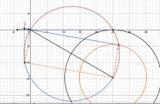
As requested by 2wice, here is the mathematics describing the skating torque equation for this configuration. I assume a frictionless bearings. Building friction into a model is always a crapshoot IMO. I choose to avoid, or at least postpone, bearing friction considerations until I at least understand the idealised model. The stylus/groove friction is the only external force considered and the model describes the system at an equilibrium where the stylus follows tangentially a locked circular groove on a disc rotating at a constant RPM.
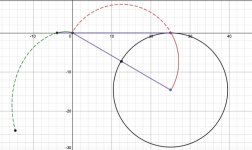
Looking at the diagram 1, the dotted lines at the stylus end of the tonearm represent the frictional drag force F, tangentially to the groove, and the inward skating force S.
At the tonearm rear, for modelling purposes the rear end path can be considered as a smooth wire (frictionless) followed by a threaded bead or small hoop, attached to the tonearm. The rear path/tonearm reaction force, is orthogonal to the path for zero friction. This orthogonal reaction N (orange) has a component along the tone arm (blue), and a component orthogonal to the tonearm (mauve).
At an equilibrium, the forces along the tonearm must balance out. Similarly the torques about the horizontal pivot must balance. Call the angle between the normal force reaction and the tone arm, beta. Then the component along the tone arm (blue) must equal and oppose the frictional drag force F.
N cos(beta) = F
The component orthogonal to the tonearm is
N sin(beta) = F sin(beta)/cos(beta) = F tan(beta).
This force component orthogonal to the tonearm, produces a torque of magnitude
T = F tan(beta)(rho)
where rho is the distance from the tonearm end to the pivot.
At equilibrium, this torque is countered by the skating torque S, at the stylus. Hence
S= T= F tan(beta)(rho). Since F depends on many unknown parameters, all we can say is
S/F = (rho) tan(beta).
Now it gets interesting! (but only if you like mathematics). The stylus path coordinates, can be expressed in terms of a parameter, the radial distance r from the disc centre. Likewise for the end path coordinates. Also the end path distance from the pivot (rho) can be expressed in terms of r. This will determine beta and hence tan(beta) in terms of r, the stylus radial distance from the LP centre. After all the dust has settled it turns out that
S/F = (rho) tan(beta) = r
This can be verified geometrically in Diagram 2, by observing the right angled triangle in the 2nd and 3rd quadrants with vertices the origin, the tonearm rear, the intersection of the straight lines in the 3rd quadrant, has beta for one interior angle with adjacent side rho and opposite side r, hence tan(beta) = r/rho or (rho) tan(beta) = r, as claimed.
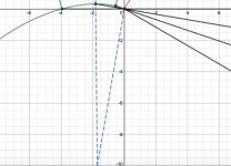
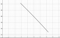
Also Diagram 3 shows the variation in the angle beta between the outer and inner grooves. It indicates that the rear reaction force is primarily orthogonal to the tonearm, the skating force. The reaction component opposing the friction drag is minor by comparison.
As requested by 2wice, here is the mathematics describing the skating torque equation for this configuration. I assume a frictionless bearings. Building friction into a model is always a crapshoot IMO. I choose to avoid, or at least postpone, bearing friction considerations until I at least understand the idealised model. The stylus/groove friction is the only external force considered and the model describes the system at an equilibrium where the stylus follows tangentially a locked circular groove on a disc rotating at a constant RPM.
Looking at the diagram 1, the dotted lines at the stylus end of the tonearm represent the frictional drag force F, tangentially to the groove, and the inward skating force S.
At the tonearm rear, for modelling purposes the rear end path can be considered as a smooth wire (frictionless) followed by a threaded bead or small hoop, attached to the tonearm. The rear path/tonearm reaction force, is orthogonal to the path for zero friction. This orthogonal reaction N (orange) has a component along the tone arm (blue), and a component orthogonal to the tonearm (mauve).
At an equilibrium, the forces along the tonearm must balance out. Similarly the torques about the horizontal pivot must balance. Call the angle between the normal force reaction and the tone arm, beta. Then the component along the tone arm (blue) must equal and oppose the frictional drag force F.
N cos(beta) = F
The component orthogonal to the tonearm is
N sin(beta) = F sin(beta)/cos(beta) = F tan(beta).
This force component orthogonal to the tonearm, produces a torque of magnitude
T = F tan(beta)(rho)
where rho is the distance from the tonearm end to the pivot.
At equilibrium, this torque is countered by the skating torque S, at the stylus. Hence
S= T= F tan(beta)(rho). Since F depends on many unknown parameters, all we can say is
S/F = (rho) tan(beta).
Now it gets interesting! (but only if you like mathematics). The stylus path coordinates, can be expressed in terms of a parameter, the radial distance r from the disc centre. Likewise for the end path coordinates. Also the end path distance from the pivot (rho) can be expressed in terms of r. This will determine beta and hence tan(beta) in terms of r, the stylus radial distance from the LP centre. After all the dust has settled it turns out that
S/F = (rho) tan(beta) = r
This can be verified geometrically in Diagram 2, by observing the right angled triangle in the 2nd and 3rd quadrants with vertices the origin, the tonearm rear, the intersection of the straight lines in the 3rd quadrant, has beta for one interior angle with adjacent side rho and opposite side r, hence tan(beta) = r/rho or (rho) tan(beta) = r, as claimed.
Also Diagram 3 shows the variation in the angle beta between the outer and inner grooves. It indicates that the rear reaction force is primarily orthogonal to the tonearm, the skating force. The reaction component opposing the friction drag is minor by comparison.
Attachments
This can be verified geometrically in Diagram 2, by observing the right angled triangle in the 2nd and 3rd quadrants with vertices the origin, the tonearm rear, the intersection of the straight lines in the 3rd quadrant, has beta for one interior angle with adjacent side rho and opposite side r, hence tan(beta) = r/rho or
(rho) tan(beta) = r, as claimed.
I meant Diagram 1.
All you have to do is add counter torque to the fixed horizontal pivot and skating goes poof. (Zero product property).
As I see it, with the sliding geometry, any antiskate must act purely orthogonal to the tonearm. It is not an issue for fixed pivot tonearms. That is one reason why I favour magnetic antiskate. It is also friction free.
Can you show an example of what you are proposing? Bear in mind the sliding nature of the pivot, the tonearm will respond to non-orthogonal forces.Yes and if you want an anti-skating torque changing with stylus position, just apply a special cam profile.
As I see it, with the sliding geometry, any antiskate must act purely orthogonal to the tonearm. It is not an issue for fixed pivot tonearms. That is one reason why I favour magnetic antiskate. It is also friction free.
Orthogonal to which plane? The one the tangent to groove force lies on? Also, what convinces you that a variable anti-skate is required?
A tangential tracking pivoting tonearm #19
My post #17 described the geometric viewpoint of the proposed tangentially tracking tonearm and #18 gave a mathematical justification for the result describing the skating torque.
After some reflection, I discovered that the rear reaction calculation too is part of the Thales circle ecology and the geometric viewpoint even determines the normal vector at the tonearm rear path. This is not too surprising, since the rear path is determined by the Thales stylus path. It is pleasing how it all falls into place. Ahh, the beauty of mathematics. The rear reaction vector is determined by the lower Thales semicircle.
Attachments
After some reflection, I discovered that the rear reaction calculation too is part of the Thales circle ecology and the geometric viewpoint even determines the normal vector at the tonearm rear path. This is not too surprising, since the rear path is determined by the Thales stylus path. It is pleasing how it all falls into place. Ahh, the beauty of mathematics. The rear reaction vector is determined by the lower Thales semicircle.
It is really beautiful. I remember someone said that a correct theory is a beautiful one.
I mean something similar to the Mayware Formula IV or V tonearms, where a weight pulls a thread that touches the arm holder at a fixed radius. Only difference is the radius should be variable (oval shape). The thread is fixed to the bearing at a certain point of its perimeter, but it is always tangential to the round part of the arm holder (in case of fixed radius). It can be optimized for variable radius, too.Can you show an example of what you are proposing? Bear in mind the sliding nature of the pivot, the tonearm will respond to non-orthogonal forces.
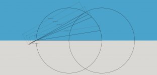
Bon,
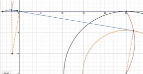
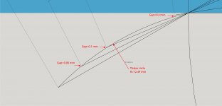
I was really inspired by your work and decided to do some further investigation. I did a diagram based on yours. It was done in Sketchup. I found that your following statement may need slightly modified.
You may see from the diagram. There are some gaps from the path of the Thales circle. But in reality, the gaps may be neglectable since these tiny gaps may convert very small tracking errors.
Please correct me if my methodology is incorrect.
Jim
I was really inspired by your work and decided to do some further investigation. I did a diagram based on yours. It was done in Sketchup. I found that your following statement may need slightly modified.
After some reflection, I discovered that the rear reaction calculation too is part of the Thales circle ecology and the geometric viewpoint even determines the normal vector at the tonearm rear path. This is not too surprising, since the rear path is determined by the Thales stylus path. It is pleasing how it all falls into place. Ahh, the beauty of mathematics. The rear reaction vector is determined by the lower Thales semicircle.
You may see from the diagram. There are some gaps from the path of the Thales circle. But in reality, the gaps may be neglectable since these tiny gaps may convert very small tracking errors.
Please correct me if my methodology is incorrect.
Jim
Attachments
Last edited:
- Home
- Source & Line
- Analogue Source
- A tangential tracking pivoting tonearm