That has nothing to do with the THD.
That's not so obvious to me.
With symmetric bias resistors seconds is lowered by 2dB.
Last edited:
That's not so obvious to me.
With symmetric bias resistors seconds is lowered by 2dB.
OK so how about lowering it 50dB, a perfectly symmetrical circuit has no even order distortion.
I'm not sure you get it either but that's OK.Richard, you clearly don't get it. No need to further continue this.
I hope I've given you an accurate and unbiased summary of Duraglit's 'shortcomings'

_________________________________
Also you have moved from a Wonky Virtual Earth similar to Duraglit with Common Earth noise behaviour to plain Common Base. This has a best NF of 3dB so exact matching to your source resistance becomes important.
Guru Hans' circuit 4 in #655herve00fr said:I don't understand a word of what you say. Your circuit is a common base as 99% of the thread circuits.
is a Wonky Virtual Earth.
For da pedants, I should have said
"from a Common Base with Wonky Virtual Earth Noise Performance similar to Duraglit with Common Earth noise behaviour to plain Common Base." It's Wonky cos as syn08 says in #658, ".. the loop gain is not easily there."
JC's patented circuit (improved by Lee in #130) is another Wonky Virtual Earth though with much greater demands on PSU noise.
These all have identical noise and probably identical THD spectra, input Z bla bla at audio frequencies. RF stuff will be different cos the parasitic capacitances do different things.
syn08 analyses plain Common Base noise around #561
As this thread is about ultra LoNoise, I was using syn08's 'definition' of plain Common Base noise in #561.Secondly you need to drop this false idea of what a "plain" common base amplifier is. They are all simply common base amplifiers, signal voltage or current is the operating principle not power transfer.
You (in #469, 500 & 501) and syn08 (in #528) show Duraglit doesn't have this "plain Common Base" noise behaviour.
Guru Hans in #655, explains this by showing 'Common Base' Duraglit is actually a re-arranged Wonky Virtual Earth.
I'll continue to refer to it as a WVE cos this topology is convenient for design of formal subsonic filtering which I like to build into phono preamps. I would have to put some beach bum projects on hold to resurrect my single brain cell and get LTspice working again so don't expect anything soon.
I'll try to remember to call it by its proper name, CBwWVENP (Common Base with Wonky Virtual Earth Noise Performance)
Incidentally, does Herve's #1416 have the #469, 500, 501 & 528 noise behaviour? I can't quite see this but I don't have a brain the size of a planet or a working LTspice installation. Herve reports only slightly worse noise than true Duraglit.
I realised this immediately after posting but hoped no one would notice. I did add the probablyBTW the contribution to noise (trivial) of the FET in this single ended circuit is obvious from inspection.
just in case.Not sure where you got that stuff "about what Brit. etc. audio gurus ... was simply wrong" If you are referring to GG Baxandall, I'd be interested in which of his prophecies you consider in errorI don't care about what Brit. etc. audio gurus wrote about phono reproduction 60 yr. ago some of it was simply wrong. The nonsense of mechanical damping via pre-amp input impedance persists even right now from folks that really should know better.
And please don't lump me with da deaf Golden Pinnae who believe in mechanical damping via pre-amp input Z. I've shown, on a number of occasions, how to calculate the EXACT value of this ... to demonstrate it is far too small be significant.
That's rubbish! You need to use a piece of coral which hasn't been damaged by Bleaching and Global Warming from the Great Barrier Reef.You would do as much by putting a head of garlic on top of your record clamp.
I still have a small stock. Send me US$100 in used bank notes at Cooktown Recording and Ambisonic Productions for a sample which will last at least 3 mths. No Confederate money please.
Last edited:
That should of course be .. with Common Emitter noise behaviour ...... with Common Earth noise behaviour ...
Mea maxima culpa
_______________
Thanks to Guru Wurcer for helping Herve with his LTspice THD sims
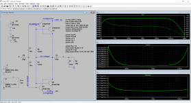
I have to clarify what I said the other day. I didn't realize how large and unbalanced the Cjc and Cje were on these ZTX devices. It turns out that is enough to create significant seconds that increase with frequency. Paralleling devices only makes it worse, I was only looking at the basic circuit with one of each transistor.
I have to clarify what I said the other day. I didn't realize how large and unbalanced the Cjc and Cje were on these ZTX devices. It turns out that is enough to create significant seconds that increase with frequency. Paralleling devices only makes it worse, I was only looking at the basic circuit with one of each transistor.
These ZTXs are power transistors crammed in a TO-92. As I said, there are many power transistors that fit the bill of "low noise". The whole shtick is the DIY friendly package (or I should say "easy to fit in Duraglit can").
The beauty of the old (now unobtanium) low noise transistors was the unique combination of low rbb and high beta, making for a very small input current noise. I have some N/P Toshibas with Rbb<3ohm and beta~1000 up to Ic=10mA.
Where do the seconds come from on your symmetrical circuit? You will find not using the .options plotwinsize=0 can cause this. The transconductance of NPN vs PNP can't possibly have that much asymmetry at the same current.
Scott, the data compression was deacitvated so I didn't need the option. I doubt the compression can cause a so large effect.
OK so how about lowering it 50dB, a perfectly symmetrical circuit has no even order distortion.
Welcome to the imperfect symmetrical circuit world.
Herve I suggest you do a web search for all the other folks that can't get the FFT spectra in LTSpice to make sense. There are several tutorials on how to undo most of the problems.
Many thanks for your suggestion, I've only been designing analog asics for just under 25 years, so I'm still a bit new to analogue electronics, signal processing and simulations.
Instead of considering that a 500µV input signal no longer allows a simplistic small signals analysis, I will scrupulously follow your suggestion.
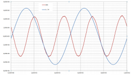
As a useless homework, I extract the distortion of the output signal (dist in red on the plot) : absolutely no trace of seconds...
Attachments
I've only been designing analog asics for just under 25 years, so I'm still a bit new to analogue electronics, signal processing and simulations.
I think Scott's got you beat by at least 12 years. Here is one of his publications from 1982. Submitted in June, see footnotes on page 1. Out of respect for the copyright holder, I deleted the bulk of the material. Out of respect for Scott, I left the biography with author photo.
_
Attachments
I think Scott's got you beat by at least 12 years. Here is one of his publications from 1982. Submitted in June, see footnotes on page 1. Out of respect for the copyright holder, I deleted the bulk of the material. Out of respect for Scott, I left the biography with author photo.
_
Thanks for the thought but I am willing to admit in this casual chat format I might have assumed things that were not true. The issues with the LTSpice FFT tool are well known, and many folks have problems getting clean results. With the original circuits using one of each NPN and PNP transistor there is a considerable increase in seconds when the PNP is replaced by a current source. I don't see the point in posting pictures to prove my point and I never meant to make any comment that should be taken personally.
To elaborate a little, the simplest circuit with floating battery power has both transistors always at the same Ic so the same Vbe equation. I was curious as to where significant asymmetry could come from so I explored and found the unexpected capacitance unbalance.
BTW if you turn the compression on in LTSpice you can get several orders of magnitude worse harmonics even looking at the voltage on an ideal source.
Last edited:
Excuse me if I'm pontificating from the wrong orifice Herve ... I'm only an ex pre10 wannabe LTspice guru .. But if the blue S/R trace in #1449 is your 20kHz 'fundamental', the red dist trace is almost all 2nd harmonicAs a useless homework, I extract the distortion of the output signal (dist in red on the plot) : absolutely no trace of seconds...
Did you post the wrong pic? ... or is this an example of decadent Western humour which us insclutabel Olientals have difficulty understanding?
I think Scott's got you beat by at least 12 years. Here is one of his publications from 1982. Submitted in June, see footnotes on page 1. Out of respect for the copyright holder, I deleted the bulk of the material. Out of respect for Scott, I left the biography with author photo.
_
Mark, you misinterpret what i said, which is easy with my bad english. I read Scott posts with all due respect.
I have to clarify what I said the other day. I didn't realize how large and unbalanced the Cjc and Cje were on these ZTX devices. It turns out that is enough to create significant seconds that increase with frequency. Paralleling devices only makes it worse, I was only looking at the basic circuit with one of each transistor.
Reducing Cjc & Cje to a few fF decrease the H2 by ~20dB and make H3 disappear.
Excuse me if I'm pontificating from the wrong orifice Herve ... I'm only an ex pre10 wannabe LTspice guru .. But if the blue S/R trace in #1449 is your 20kHz 'fundamental', the red dist trace is almost all 2nd harmonic
Did you post the wrong pic? ... or is this an example of decadent Western humour which us insclutabel Olientals have difficulty understanding?
As my humour is worse than my English, it means that I am still worse with Excel than with LTspice or that I do not see anything anymore.
Here is another possible design which need at least a soft start in order not to burn the trans at power-on and show a very bad PSRR.
Attachments
@Bonsai,
Lying far away on a beach, I took the time to look at your nice compendium.
For all Duraglit variants with external gnd referenced power supplies, such as the Newton, the Weinberg, the Archimedes etc, there should be a large cap in series with the Cart to prevent DC current from flowing into the Cart because of hfe differences between NPN and PNP.
No such thing is needed with a floating battery or solar cell powered version.
Hans
I hope the beach is nice!
I thought about that, but did not put any caps in because Scott and billshurv have said on a number of times its not needed.
Just sayin': if an input cap is not needed, then the whole head amp with floating power supply concept (from Leach and Duraglit, to the Hawksford LFD phono stage) is rendered useless. Any low noise, DC coupled, bipolar amplifier would work just fine as a head amp.
I thought about that, but did not put any caps in because Scott and billshurv have said on a number of times its not needed.
I don't recall saying that categorically just that it requires thought and is sometimes not needed especially with FET based circuits that often don't have a mechanism for current in the cart.
??????Just sayin': if an input cap is not needed, then the whole head amp with floating power supply concept (from Leach and Duraglit, to the Hawksford LFD phono stage) is rendered useless.
Is this good enough ?I hope the beach is nice!
Attachments

- Home
- Source & Line
- Analogue Source
- Richard Lee's Ultra low Noise MC Head Amp