Here they are.
No change since #1379.
Thank you. I missed/forgot the earlier post.
Not so much, but the jfet as input current sink is not so common and allow high gain.
You lose the cancellation of seconds by removing the symmetry, for some carts where you want less step up it might matter.
You lose the cancellation of seconds by removing the symmetry, for some carts where you want less step up it might matter.
Of course, and the single ended is better on third.
You won't get your 'high' gain in any practical situation. Your #1416 circuit has input Z of 2R5 😱Not so much, but the jfet as input current sink is not so common and allow high gain.
I'm also suspicious of your noise results as the noise of the FET and its resistor seems to be missing in action.
Do you have a real life application in mind or is this just a SPICE world exercise?
If so, what is the application? What gain do you want/need?
What are your power supplies?
Last edited:
What level of 3rd do you get?Of course, and the single ended is better on third.
At what input level?
Is that with your 1p source resistance?
You won't get your 'high' gain in any practical situation. Your #1416 circuit has input Z of 2R5 😱
I don't understand your argument as the input Z is close to the other circuit as your.
I'm also suspicious of your noise results as the noise of the FET and its resistor seems to be missing in action.
I provided the models I used. If something is wrong inside, tell us.
Do you have a real life application in mind or is this just a SPICE world exercise?
I don't know yet, I use a MM cart.
What level of 3rd do you get?
At what input level?
Is that with your 1p source resistance?
third is ~-103dB
output is ~43mV rms
input is 500µV peak 20kHz
Rg=5ohm
You won't get your 'high' gain in any practical situation. Your #1416 circuit has input Z of 2R5 😱
I don't claim 51dB gain. Duraglit can have as high a gain as your circuit .. and also less noise, THD bla blaI don't understand your argument as the input Z is close to the other circuit as your.
The reason the FET noise doesn't show is cos you are measuring Short Circuit Input Noise. Your 1p source resistance shorts out the FET noise.I'm also suspicious of your noise results as the noise of the FET and its resistor seems to be missing in action.
If you have a real input source resistance, the FET noise will probably dominate. Also you have moved from a Wonky Virtual Earth similar to Duraglit with Common Earth noise behaviour to plain Common Base. This has a best NF of 3dB so exact matching to your source resistance becomes important.
Do you have a real life application in mind or is this just a SPICE world exercise?
Why don't you choose a MC cartridge you might buy and use its source resistance for your LTspice sims.I don't know yet, I use a MM cart.
You can then compare Duraglit and your circuit for noise & THD at the same current & gains. My original document has details of the matching as I thought Duraglit was also plain Common Base until put right by Guru Hans. The 'matching' will be close to what's needed for your circuit .. but you can easily twiddle the sim current for best results with your circuit & source resistance.
Just curious Richard, do you think the Duraglit has any shortcomings? You keep trying to "sell" it as the best thing since sliced bread. To me, the only real plus I see is it's simplicity and therefore the ability to quickly cobble it in a Duraglit can. Otherwise, I find it completely improper for anybody but those willing to tweak it after cobbling together the two transistors and three resistors.
BTW, you can look at it whatever way you want, Duraglit it is still a common base circuit. From an AC perspective, assuming identical P/N transistors, you can fold the schematic along a mid horizontal line and you'll get exactly a common stage base, built with one transistor with double gm, double Cbc and Cbe, half output impedance, etc... If you disagree with this assesment, you need to say what exactly is in your view a common base stage and why the Duraglit is not one. You know, it looks, walks, and quacks like one... BTW, make no mistake, #375 is as much a common base, as almost everything else in this thread.
BTW, you can look at it whatever way you want, Duraglit it is still a common base circuit. From an AC perspective, assuming identical P/N transistors, you can fold the schematic along a mid horizontal line and you'll get exactly a common stage base, built with one transistor with double gm, double Cbc and Cbe, half output impedance, etc... If you disagree with this assesment, you need to say what exactly is in your view a common base stage and why the Duraglit is not one. You know, it looks, walks, and quacks like one... BTW, make no mistake, #375 is as much a common base, as almost everything else in this thread.
The big one is the need for clean floating power supply.Just curious Richard, do you think the Duraglit has any shortcomings?
But you have provided a solution to this with your Solar Cell / LED experiments. I would love more details of the behaviour of these under load so we can tailor one to provide zillion mA to a true Duraglit.
Of course, this 'shortcoming' could be considered a PRO. Both you and Bonsai have amply demonstrated the difficulties & complexities of providing clean power to a very LN input stage.
On that basis, the single floating alkaline C cell solves many problems at a stroke .. just not to those who wish to build a very LN headamp into a mains powered device 🙁 For this your Solar Cell / LED is more appropriate. 🙂
Actually its the "ability to quickly cobble it in a Duraglit can and achieve SOTA noise and pretty good THD too"To me, the only real plus I see is it's simplicity and therefore the ability to quickly cobble it in a Duraglit can.
By SOTA, I mean Duraglit has better noise than any other solution running the same input current and number of input devices and usually better THD too (let alone solutions with the same total current and total number of devices).
If like Gerhad, you need HiZ input and precise gain, other, much more complex solutions, are appropriate but still probably won't achieve Duraglit's noise performance.
But Duraglit is perfect for LoZ MC cartridges. Its simplicity & small size also means the PCB layout is likely to have a better chance of being laid out properly for LN.
Actually, one of its strengths is you don't have to tweak it. The instructions in my original document are sufficient, with no further tweaking, to obtain better performance than any device except your #375.Otherwise, I find it completely improper for anybody but those willing to tweak it after cobbling together the two transistors and three resistors.
In fact, with what this thread has discovered, these instructions can be simplified to obtain even better performance than I envisaged ... including beating #375 🙂 .. but this requires someone to build a Solar Cell / LED powered Duraglit and measure it.
.. but it doesn't hiss like one. 😱BTW, you can look at it whatever way you want, Duraglit it is still a common base circuit. From an AC perspective, assuming identical P/N transistors, you can fold the schematic along a mid horizontal line and you'll get exactly a common stage base, built with one transistor with double gm, double Cbc and Cbe, half output impedance, etc... If you disagree with this assesment, you need to say what exactly is in your view a common base stage and why the Duraglit is not one. You know, it looks, walks, and quacks like one...
You and Guru Wurcer have pointed out Duraglit's noise performance isn't like plain Common Base, which has Rnv = 1/2gm and Rni = 2/gm so a best NF of 3dB if matched to the source.
Guru Hans, in a display of insight worthy of Great Guru Baxandall, 😱 explains this by showing Duraglit's noise & THD performance is that of a Wonky Virtual Earth in #655 Wonky Virtual Earths are Common Emitter with the same Rnv as plain Common Base but Rni = 2hfe/gm so have a wider range of good NF and a 'best-match NF' much better than 3dB.
GG Baxandall was fond of re-arranging circuits to show their equivalence.
Please don't be offended if I regard #375 as a Duraglit with extra bits added to solve, IMveryHO, imaginary problems .. but only degrade performance slightly 😉BTW, make no mistake, #375 is as much a common base, as almost everything else in this thread.
Of course I'm only saying this cos until someone builds a SolarCell / LED powered Duraglit running zillion mA, I'm jealous that #375 is the quietest real-life MC head amp in da known Universe 🙂
In my book, though I do enjoy LTspice flights of fancy, only real-life items count in 'best-in-da-known-Universe' stakes. 😀
___________________
But my use of Duraglit as a reference for Herve is more prosaic than the above purple prose.
I'm suggesting he looks at noise performace with 'real-life' sources. I need to provide a 'good example' and it shouldn't be too complex so he will be more likely to get reliable results in SPICE world.
Duraglit serves as a simple example of SOTA noise (& sorta THD)
Last edited:
Many thanks to Hans and aboos for their work on matching Duraglit devices without emitter resistors for both hfe & Vbe.Adding a second set of parallel transistors to the Duraglit, will also reduce noise by 3db in a simulation !
Here the Richard and Herve versions, where the Duraglit scores lower in noise.
The pure simplicity of the Duraglit, despite some Hfe concerns, is still a thing of beauty to my eyes.
My criteria for 'matching' devices was simply rbb' be effectively halved when you doubled the number of devices. You can test this by making rbb' the dominant noise source in your test jig .. ie Short Circuit noise on a Duraglit running high current and high gain should drop by 3dB
You see this with old fashioned 'LN' transistors like BC384/184/214 in the original WW article at the start of my original document.
I tested about a 100 examples each of Olde Unobtainium transistors too and always got the 3dB improvement in the 1V5 C cell powered Duraglit.
IIRC, this serendipitious situation didn't hold with the original Leach versions with 9V PP3 and greater Vbe .. but senile memory may mean I'm pontificating from the wrong orifice. 😱
I spent a lot of time in Jurassic times trying to get a formal handle on dis matching business but the only thing that survives is this cryptic note
"Paralleling BJTs: thermal instability beyond 20% only if you violate Ic * Pd < 460u for TO92 package with transistors thermally coupled."
Certainly with pure Duraglit, if you need more than 1 pair of ZTX851/951, there is no need to select transistors provided they are from the same batch. EVIL emitter resistors just add noise.
I wouldn't bother thermal coupling 2 pairs but may do if Eric & I ever get our Transformerless Ribbon mike with zillion ZTX851/951 pairs off the ground.
Thermal coupling for log conformance is important .. as in Baxandall's swept oscillator
I don't claim 51dB gain. Duraglit can have as high a gain as your circuit .. and also less noise, THD bla bla
I have no doubt about that.
The reason the FET noise doesn't show is cos you are measuring Short Circuit Input Noise. Your 1p source resistance shorts out the FET noise.
If you have a real input source resistance, the FET noise will probably dominate.
This is not correct.
The jfet noise (as the bip noise) is present even if the input is shorted to ground.
When I sim with a resistive source the dominant noise come from the input resistor.
Also you have moved from a Wonky Virtual Earth similar to Duraglit with Common Earth noise behaviour to plain Common Base. This has a best NF of 3dB so exact matching to your source resistance becomes important.
I don't understand a word of what you say. Your circuit is a common base as 99% of the thread circuits.
You can then compare Duraglit and your circuit for noise & THD at the same current & gains. My original document has details of the matching as I thought Duraglit was also plain Common Base until put right by Guru Hans. The 'matching' will be close to what's needed for your circuit .. but you can easily twiddle the sim current for best results with your circuit & source resistance.
Impedance matching doesn't matter here.
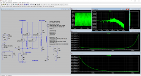
Here is a complete set of sims with Rg = 10 ohm
RTI noise is 448pV/rtHz dominated by Rg and not by the jfet.
Attachments
I don't understand a word of what you say.
Don't worry, you are not alone. Richard is using very strange methods (today) to charcterize noise and other parameters. This was discussed in extenso in this thread, and after several pages of back and forth it turned out that he is using S/N ratio as a noise metric, not the input referred noise as almost everybody today.
"Noise matching" comes from the optimum source impedance to maximize the S/N ratio, like in the low noise bipolar transistors data sheets. His "language" roots in the mid last century broadcasting environment equipment characterization, nothing wrong with that, only that today we are using a much more effective way to charcterize and compare noise performance.
Add to this technically outdated discourse Richard's propension for a colorful "Duraglit" based language, full of obscure concepts that only he understands ("Wonky Virtual Earth", "Common Earth noise", etc...) and you'll get the whole picture. BTW, I was never able to look at the "document" he is mentioning every other post, can't find it anywhere.
Richard, in my engineering book, a circuit that has the performance beta and temperature dependent is not worth considering today. Last century was probably different. To me, simple and simplistic do not overlap.
Last edited:
[/B]You and Guru Wurcer have pointed out Duraglit's noise performance isn't like plain Common Base, which has Rnv = 1/2gm and Rni = 2/gm so a best NF of 3dB if matched to the source.
I agree with syn08, first off why are you so defensive? Secondly you need to drop this false idea of what a "plain" common base amplifier is. They are all simply common base amplifiers, signal voltage or current is the operating principle not power transfer. BTW the contribution to noise (trivial) of the FET in this single ended circuit is obvious from inspection.
I don't care about what Brit. etc. audio gurus wrote about phono reproduction 60 yr. ago some of it was simply wrong. The nonsense of mechanical damping via pre-amp input impedance persists even right now from folks that really should know better. You would do as much by putting a head of garlic on top of your record clamp.
@herve It is easy to get the floor on the FFT down to -220dB and clearly see the harmonics the thirds don't vary as much as the large increase in seconds. BTW I absolutely hate the LTSPICE FFT tools, we had two versions of transient analysis the normal one and one where the results where for Fourier analysis, you could always get the -300dB floor of 64bit floats in the spectra.
Last edited:
Can you repeat your sims with Duraglit?Here is a complete set of sims with Rg = 10 ohm
RTI noise is 448pV/rtHz dominated by Rg and not by the jfet.
Use Rg=10R, 2 x ZTX851, 2 x ZTX951, 10mA total current and adjust your 'gain' to have conditions the same as with your circuit
Last edited:
Can you repeat your sims with Duraglit?
Use Rg=10R, 2 x ZTX851, 2 x ZTX951, 10mA total current and adjust your 'gain' to have conditions the same as with your circuit
Richard,
The numbers I gave were only to demonstrate that what you say on the jfet noise was not correct.
Your circuit in these conditions give ~435 pV/rtHz, mine is 448
@herve It is easy to get the floor on the FFT down to -220dB and clearly see the harmonics the thirds don't vary as much as the large increase in seconds. BTW I absolutely hate the LTSPICE FFT tools, we had two versions of transient analysis the normal one and one where the results where for Fourier analysis, you could always get the -300dB floor of 64bit floats in the spectra.
Scott, I disagree, you can see on the plot that "the large increase in seconds" is +5.5dB as the variation on thirds is -7.5dB. Of course the THD is better on the symmetric circuit.
Attachments
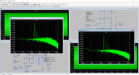
Scott, I disagree, you can see on the plot that "the large increase in seconds" is +5.5dB as the variation on thirds is -7.5dB. Of course the THD is better on the symmetric circuit.
Where do the seconds come from on your symmetrical circuit? You will find not using the .options plotwinsize=0 can cause this. The transconductance of NPN vs PNP can't possibly have that much asymmetry at the same current.
Last edited:
Where do the seconds come from on your symmetrical circuit?
To have a symmetric power supply, bias resistors must be different because of different hfe.
I try the .options with no change.
Attachments
Last edited:
To have a symmetric power supply, bias resistors must be different because of different hfe.
That has nothing to do with the THD.
- Home
- Source & Line
- Analogue Source
- Richard Lee's Ultra low Noise MC Head Amp