Neons are pretty ancient technology, and electrically they can be very noisy. When this TT was current, LED's were very inefficient and gave little more than a dull moderate glow when run at around 20 milliamps or more. Modern ones can be blindingly bright on just a milliamp or so.
Reverse breakdown voltage is low but its a condition it doesn't see in this circuit. With the transistor off nothing flows. When on the LED drops around 2V leaving the rest across the resistor.
The only refinement I could think of would have been to pulse the LED rather than have it on/off but I'm not sure how that would look strobe wise.
Whatever takes your fancy, pick the colour you want (perhaps red or orange for starters) and take it from there.
These things are just so cheap that you can try several. Lots of different package outlines are available as well. The 10,000 mcd rating tells you this is ultra bright for little current, early LED's were literally 1000's of times less than this.
https://cpc.farnell.com/kingbright/l-7113sec-h/led-5mm-10000mcd-red-orng-clear/dp/SC08053?st=LED
https://cpc.farnell.com/broadcom-limited/hlmp-k401/led-3mm-orange/dp/SC11559?st=LED
3mm and 5mm are the common sizes. A tiny one with leads bent to 90 degree might be another option as that would shine 'outwards'.
https://cpc.farnell.com/kingbright/l-2060ed/led-1-8mm-orange/dp/SC07613?st=LED
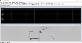
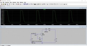
This shows the standard circuit running on 34 volts and also the addition of a cap and resistor to give more of a short duration pulse. Resistor can be varied to suit. Its all matter of seeing what gives the most pleasing visual impact and strobe clarity. Alter the 12k to alter the brightness. The trace is showing the LED current.
Attachments
Two points:
1/ If the LED is just 'any old LED' then it may not be very efficient. High efficiency ones really are light years ahead in terms of brightness.
2/ I'm taking the printed circuit diagram at face value which shows a square wave drive signal to the transistor. The amplitude will be clamped by the B-E junction to 0.7V but the important detail is whether the signal had a 50:50 duty cycle. In other words its high for the same amount of time it is low. The LED is on for as long as it is off.
If that waveform wasn't 50:50, say it was 10:90 then the LED would only be on for 10% of the time and so look dimmer than you would expect.
A good check on LED brightness is just to connect one via a resistor across a 9 volt battery and check the current vs brightness.
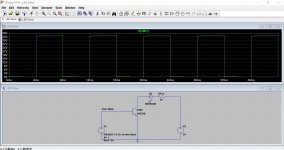
Also check with the scope that the collector of the switching transistor is getting close to zero volts. It should look like this with the transistor being either fully on or fully off:
1/ If the LED is just 'any old LED' then it may not be very efficient. High efficiency ones really are light years ahead in terms of brightness.
2/ I'm taking the printed circuit diagram at face value which shows a square wave drive signal to the transistor. The amplitude will be clamped by the B-E junction to 0.7V but the important detail is whether the signal had a 50:50 duty cycle. In other words its high for the same amount of time it is low. The LED is on for as long as it is off.
If that waveform wasn't 50:50, say it was 10:90 then the LED would only be on for 10% of the time and so look dimmer than you would expect.
A good check on LED brightness is just to connect one via a resistor across a 9 volt battery and check the current vs brightness.
Also check with the scope that the collector of the switching transistor is getting close to zero volts. It should look like this with the transistor being either fully on or fully off:
Attachments
 ) I'll test another of the same type with a 9V battery and different resistors, as you suggest. Then I'll scope the switching transistor.
The important thing with the collector waveform is that it bottoms out at zero volts. That means the full 34 volts is available to the LED + resistor. When off the collector should rise to virtually the supply voltage.
Sounds like you might need some high efficiency LED's. It might be worth bringing wires out for the LED while testing and then you can hold them near the platter and judge the effect
Neons such as originally fitted are usually pretty dim things anyway.
Sounds like you might need some high efficiency LED's. It might be worth bringing wires out for the LED while testing and then you can hold them near the platter and judge the effect
Neons such as originally fitted are usually pretty dim things anyway.

Ah...
Now that shows the duty cycle is nowhere near 50:50. The LED is only on during that dip when the collector voltage falls. The scope should be DC coupled for this test and you should set the scope trace to say that bottom line on the screen.
1/ Set the scope input coupling switch to 'ground'
2/ Move the trace down using the shift knob to either the very bottom horizontal line or the one one above (either will do). That is now our reference point. All positive voltage will now be above that line.
3/ Set the coupling to DC.
You should now see the bottom part of the waveform make it all the way down to ground reference . That proves the LED is seeing the full change in voltage.
I think you also probably need to try some different LED's tbh.


Interesting. I would have thought the collector would have got a bit lower tbh but in absolute terms its switching cleanly.
The transistor is driven fully on (saturated) or fully off (cut-off) and when saturated it should be seeing little voltage across the emitter collector junction.
The transistor fitted is a high voltage type which we don't now need with it running on 34 volts. That could be one reason its not hitting ground.
A small signal modern device could be fitted like a BC546. Pretty much anything will work here as long as its rated at 50v or over.
Its up to you really. You can either stick with originality and try and find a neon that works OK or experiment with LED's
You mean replacing the transistor? Nothing lost in doing that, a modern high gain small signal part will be much better suited than an old high voltage and relatively low gain device. It may not make much obvious difference, its just the satisfaction of having something more suitable fitted.
Its all a little bit trial and error though.
Neons are quite interesting devices actually, a bit hit and miss and affected by various factors.
Neon lamp - Wikipedia
Ok, so after experimenting with a few different LED's and current-limiting resistors, I found that the main hurdle in this application was the viewing angle of the bulb. Using a smaller LED that has a somewhat wider viewing angle (along with a 4.7k resistor), I was able to orient it in the original spot to get satisfactory illumination.
- Status
- This old topic is closed. If you want to reopen this topic, contact a moderator using the "Report Post" button.
- Home
- Source & Line
- Analogue Source
- Sony PS-X70: Deciphering motor issue