The neon would only lights when the drive transistor gets fired... again another squarewave output from the chip 🙂 Neons drop anywhere from 70 volts to ??? 100 or more when conducting. That bit of the circuit is out there on its own and can't interact with the rest of the circuitry in any way.
Going back to the Start/Stop button. . .
Currently, I measure 2V on pin 9, which then drops to a seemingly random lower value when the button is pressed. What should I expect to be seeing here?
Currently, I measure 2V on pin 9, which then drops to a seemingly random lower value when the button is pressed. What should I expect to be seeing here?
What indeed. Pin 9 gets grounded (or nearly so) via the switch when it is pressed. The 47 ohm will (I assume) be to prevent discharging cap C10 directly through the contacts.
So with the button pressed and held I would expect almost zero volts on pin 9. That proves the switch continuity is OK. What the pin rests at depends on the internals of the chip. The diagram shows 1.75 volts which basically agrees with your reading i.e not zero volts and not +5 volts.
Does pin 7 of the CX193 fall to zero volts as you press the Stop/Start button? If pin 7 is at zero volt then the start indicator D704 should light. 5 volts on pin 7 and it will not.
When I press and hold the Start/Stop button, pin 9 goes to zero volts. And when I press and release the button, the voltage at pin 7 goes from 5.20 to just about zero (0.15). The LED lights up as it should.
One more thing ruled out, I suppose. 🙄
One more thing ruled out, I suppose. 🙄
Is there any point in my testing the part of the circuit that includes Q147 and Q148? One thing I noticed is that I have -1.0V at pin 6 of the CX193, rather than zero, which is why I ask.
It could be worth looking around pin 6 I suppose. I couldn't figure out for sure where it goes as the text is to blurred on the diagram and the two points can't be joined in a straight line.
Pin 6 is shown as an output (looking at the arrow internally in the chip) and yet D161 is an output from the transistor. I think D161 goes to C14 (next to pin 6 on the diagram).
Usually any minus voltages are the result of something floating (which may be valid) or there is an AC signal there that the meter doesn't cope with.
Just looking at the block diagram... so pin 6 goes to point C I think (Q147) and D161 to C14.
D161 just pulls C14 close to ground when Q148 turns on. You could try lifting one end of the diode just to see if the symptoms change.
If pin 6 does go to point C then I can't explain the -0.6 volts. Check that with a scope and check continuity from pin 6 to wherever it goes.
Ok. So pin 6 goes to Q147 by way of R38, as well as to the anode side of D161. And you're right that the cathode side of D161 goes to C14.
I'll try lifting one leg of D161. No change.
EDIT: Strike that about pin 6 going to the anode side D161. Duh.
I'll try lifting one leg of D161. No change.
EDIT: Strike that about pin 6 going to the anode side D161. Duh.
Last edited:
Its always a case of looking for clues but I'm running out of ideas on this one I'm afraid 🙁
This is probably a bit dumb to suggest but what happens at pin 1 on the scope when you press and hold the start button and the start LED is lit. Does the sawtooth appear?
Also try the same again whilst giving the platter a spin to create the feedback signal. Anything on pin 1 then?
This is probably a bit dumb to suggest but what happens at pin 1 on the scope when you press and hold the start button and the start LED is lit. Does the sawtooth appear?
Also try the same again whilst giving the platter a spin to create the feedback signal. Anything on pin 1 then?
So no change to the waveform on pin 1 when holding the Start button, either with or without spinning the platter. What did make a difference was pressing and holding either of the Speed buttons.
From this:

To this while pressing and holding 33 RPM:

From this:
To this while pressing and holding 33 RPM:
That still looks like random internal stuff within the chip tbh. Do you know what the frequency is for interest?
If you take the scope timebase setting per division (for example if its set to 100uS per division) then take two similar points on the waveform (in this case its about 1 division) and find the reciprocal.
So 100uS becomes 1/100.e-6 which would be 10kHz
I don't think we are any nearer 🙁
If you take the scope timebase setting per division (for example if its set to 100uS per division) then take two similar points on the waveform (in this case its about 1 division) and find the reciprocal.
So 100uS becomes 1/100.e-6 which would be 10kHz
I don't think we are any nearer 🙁
I'm getting 12mV peak-to-peak and a frequency of 500kHz (timebase is 2uS and 1 division). When I press and hold the 33 rpm button, I get 18mV peak-to-peak.
So really really low amplitude, little more than noise really... it did have that look about it.
Its just internal leakage within the chip that is coupling the high frequency crystal oscillator signal to other parts.
Back to square one 🙁
I still think the clues will be in why the sawtooth oscillator isn't running, and the question is whether its being 'told' not to run or whether some input to the chip is inhibiting it in some way.
When I try to carry out the alignment, I get a 32mV peak-to-peak sine wave on pin 21. Adjusting RV2 and RV3 has no effect on the waveform.
OK, so nothing doing there as the trimmers are altered 🙁
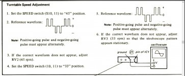
Back at the start we checked the crystal oscillator... at least by saying it 'looked OK'.
Lets be a bit more detailed on that. Does the amplitude on pin 16 approximate to the 800 mv peak/peak shown on the diagram? Only pin 16 will probably look OK which is shown as the osc output, pin 17 could be affected by the loading of the scope probe.
Does the frequency match the value on the crystal? I can't find any reference to the crystal frequency in the manual or parts list.
It's difficult to say if the waveform on pin 16 is exactly what's shown in the service manual. Similar, yes.

But the amplitude is just 10mV peak/peak. And the frequency is 500kHz. (Is that correct for 2us and one division?)
The crystal has the following printed on it. I'm assuming the first number is the frequency in Megahertz.
3.9321M
380-21
RVR2813
But the amplitude is just 10mV peak/peak. And the frequency is 500kHz. (Is that correct for 2us and one division?)
The crystal has the following printed on it. I'm assuming the first number is the frequency in Megahertz.
3.9321M
380-21
RVR2813
- Home
- Source & Line
- Analogue Source
- Sony PS-X70: Deciphering motor issue