So...
Bearing in mind trial and error you could replace the neon with an LED, then remove D402 and C408 and then connect a link from the unregulated 34 volt rail to where the plus end of C408 was.
That would feed the LED from the 34 volt rail. The 12k resistor would be OK as a starting point and would limit the current to just around 3ma. If that was to bright (modern high efficiency LED's are really bright) then you could increase the value to suit.
Its trial and error as to the visual impact and how it looks in practice.
I've started getting lower than expected measurements on the power rails after having them pretty much on the nose post-recap.
28V instead of 34V
-31V instead of -35V
It doesn't seem like the addition of the LED bulb and circuit mod described above should have caused this, but perhaps I mis-wired something. Right now, I have the 34V coming from pin 116 (Brown wire) to the positive side of where C408 was mounted.
🙂 just remember that this is like a zillion posts back in time for me 😀 I do remember the thread though (lol how could I forget it). Was it really only just over a month ago, if you asked me I would have said March/April time or earlier...
If all the unstabilised rails are a little down and have gone that way without you doing anything then the first check is to measure the incoming mains voltage. Make a note of the value and the DC value of the rails so you have something to compare against at a later date.
If something was pulling the rails down significantly then things would be getting hot.
Sorry about that. Yes, I forgot that life went on after the first battle with this turntable. I appreciate you venturing back into the fray.
I'll check and record the mains voltage.
In terms of heat, yes Q402 and Q403 seem to be generating significantly more heat than before.
I'll check and record the mains voltage.
In terms of heat, yes Q402 and Q403 seem to be generating significantly more heat than before.
I'll have to hunt for the circuit (full manual) again so I can take a look... that's one for tomorrow 🙂
Measure the mains though, checking supplies is always the first rule of faultfinding.
Measure the mains though, checking supplies is always the first rule of faultfinding.
Ok, so for the mains voltage measured right before it goes into the power transformer, I have 121V AC.
Something odd occurred. I was measuring the voltages at the output pins (115, 116, 107 on page 24 of the service manual), when I slipped with my probe and shorted 115 to the ground pin 117, followed by the spark and immediate self-flagellation. 😱 Haven't done that in a while! Anyway, when I then rechecked the voltages, they're higher than they were prior:
Pin 116 was 28V and is now 31.5V
Pin 115 was 31V and is now 32.2V
Pin 107 has consistently been 14.4V
The voltages at the other output pins on the board are correct, except for pin 64, which is 13.4V instead of 17.5V.
Something odd occurred. I was measuring the voltages at the output pins (115, 116, 107 on page 24 of the service manual), when I slipped with my probe and shorted 115 to the ground pin 117, followed by the spark and immediate self-flagellation. 😱
Haven't done that in a while! Anyway, when I then rechecked the voltages, they're higher than they were prior:Pin 116 was 28V and is now 31.5V
Pin 115 was 31V and is now 32.2V
Pin 107 has consistently been 14.4V
The voltages at the other output pins on the board are correct, except for pin 64, which is 13.4V instead of 17.5V.
Last edited:
Pin 107 is stabilised and so it would be expected to be constant, pins 116 and 115 are unstabilised and so depend totally on the incoming mains voltage.
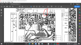
Pin 64 I can't make out as the board layout seems to show it as ground and the print layout is ground.
I suspect you probably haven't a problem here tbh.
Small transformers have very poor voltage regulation, that's one thing, and another (and I'm not sure how this would work in practice) is that the limited metal (iron) in the core means they can saturate easily which could occur if the mains was higher than normal and particularly if the mains was distorted a little (flat topped). How that would effect the output voltages under load I'm not really sure but its something to consider.
Also check the mains fuse holder is OK as they can go slack and cause a highish resistance. That scenario fits with the 'I shorted it out and now it works' theory as the sudden high current could temporarily reduce the resistance of a poor oxidised connection.
I'd just keep a check and note if the voltages seem better at different times of the day when the mains may be better/worse/higher/lower etc.
Attachments
Thank you. I hadn't considered the mains fuse being oxidized, but I'll check it and likely just replace with a new one.
The reason the lowish 28V in particular concerned me was that the table had been reading consistently higher and the drop coincided with sudden erratic operation. I'll try powering up the table through my variac, maintain a steady mains voltage, and then check those pin readings again.
Re pin 64, I mistyped. It should have been pin 65.
Ok, apparently there's no mains fuse in the U.S. version of this table. So still not sure why the short I caused resulted in 116 going back up, albeit only temporarily it seems.
Checking the voltages again, I have 120V AC coming into the transformer from the mains and pin 116 is back down to 28.6V, whereas pin 115 is holding at 32.5V and pin 65 is now the correct 17.5. Maybe you're right, and the B+ voltage at pin 16 just is what it is because of the transformer. That said, I know it was closer to 34V previously. . . .
Another likely unrelated piece of information. I've noticed that sometimes when I power this table on, I hear a little pop at the power switch. But sometimes not. Oxidation on the contacts?
EDIT: I just looked closer at Q402 and Q403, which were generating a fair bit of heat. Well, it seems that's been the case for some time. The nylon screw head of Q402 has melted into a blob. Wondering if I should replace these.
Last edited:
The popping could just be the random surge current the transformer draws at power on. Depending on where it was on the mains cycle when you power it off will determine whether the core is magnetized or not and if it is, by how much. That then plays a part when power is reapplied in how much current is initially drawn as well as where the mains is on its cycle.
So the noise is to be expected although it could be made worse if the contacts are in poor shape. If there is no AC volt drop across the switch when on then its not affecting the transformer.
Haven't got the diagram on this PC so will have to look later at what feed pin 65.
So the noise is to be expected although it could be made worse if the contacts are in poor shape. If there is no AC volt drop across the switch when on then its not affecting the transformer.
Haven't got the diagram on this PC so will have to look later at what feed pin 65.
I would say definitely replace those. TIP41 (or TIP31) of any letter (A,B or C) should be fine.
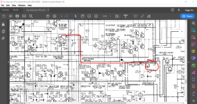
Pin 65 (17.5V) is an odd one. It is regulated (from the emitter of Q401) and it appears to supply just one opamp.
I would suggest rechecking the measurements tbh as that one shouldn't vary or be pulled down. Make sure Q401 is running cool/cold.
Pin 65 (17.5V) is an odd one. It is regulated (from the emitter of Q401) and it appears to supply just one opamp.
I would suggest rechecking the measurements tbh as that one shouldn't vary or be pulled down. Make sure Q401 is running cool/cold.
The voltage at pin 65 is back to normal: 17.5V. But I wouldn't say that Q401 is running cool per se. Using an IR thermometer, it measured a high of 99 degrees F after about 5 minutes, though I don't know how much of that could be due to the radiant heat from the large heat sink straight ahead of it.
As for Q401 (melted screw), it reached 195 degrees F, and Q402 about 130 degrees F. These two, Q401 in particular, are the hottest part of the board.
I was also looking at KSD526Y as replacements, but I'll go with the TIP41 as you suggest.
As for Q401 (melted screw), it reached 195 degrees F, and Q402 about 130 degrees F. These two, Q401 in particular, are the hottest part of the board.
I was also looking at KSD526Y as replacements, but I'll go with the TIP41 as you suggest.
Looking at the circuit and they are just series pass regulators so nothing high tech at all.
Q401, as far as I can see it only supplies an opamp... and only just spotted this by zooming in but the collector (input) has an 820 ohm series feed resistance. So I can't see there being any issue there. The circuit shows just 3 volts over that resistor which is a current of 3.5 milliamps.
Q401, as far as I can see it only supplies an opamp... and only just spotted this by zooming in but the collector (input) has an 820 ohm series feed resistance. So I can't see there being any issue there. The circuit shows just 3 volts over that resistor which is a current of 3.5 milliamps.
Attachments
Don't forget that you will need insulating kits (particularly the bushes) for metal backed transistors.
Thanks for the reminder about the insulator kit. It also appears that the heat sinks are meant to be tied together at one edge with some black silicone adhesive or some such.
As for the original problem, I have to keep thinking on this then. The erratic behavior is now less so, in that now the tonearm is consistently unresponsive to Start, Stop, or Cue commands. It's funny (not really), but this is the exact opposite of the original issue I had with this table, which was a fully-functioning tonearm and a platter than wouldn't spin. The platter spins and stops fine after the work we did earlier to diagnose the faulty crystal. In this case, I've been harping on the power supply voltage because it's the one thing that's changed since I last worked on the table (and it was working). But if there's nothing to be done to address the B+ at 28V, then I'll look elsewhere for possible culprits.
As for the original problem, I have to keep thinking on this then. The erratic behavior is now less so, in that now the tonearm is consistently unresponsive to Start, Stop, or Cue commands. It's funny (not really), but this is the exact opposite of the original issue I had with this table, which was a fully-functioning tonearm and a platter than wouldn't spin. The platter spins and stops fine after the work we did earlier to diagnose the faulty crystal. In this case, I've been harping on the power supply voltage because it's the one thing that's changed since I last worked on the table (and it was working). But if there's nothing to be done to address the B+ at 28V, then I'll look elsewhere for possible culprits.
Assuming this is a mistake in the service manual: It shows -14.5V at pin 62 on the power supply board, but it seems that it should actually be +14.5V.
Apologies for multiple posts in a row.
Trying to break this down. Since the Up/Down cue button is unresponsive (though the LED remains lit), I decided to focus on that alone. Power to the tonearm cue motor comes from the main board via a 5 pin Molex connector. While monitoring the B+ voltage on pin 116 of the power supply board, I pulled this connector. Doing so caused the pin 116 voltage to immediately rise from 28V to 32V. Reconnecting it causes it to drop back down again. How to interpret this? Short in the motor pulling down the voltage?
Trying to break this down. Since the Up/Down cue button is unresponsive (though the LED remains lit), I decided to focus on that alone. Power to the tonearm cue motor comes from the main board via a 5 pin Molex connector. While monitoring the B+ voltage on pin 116 of the power supply board, I pulled this connector. Doing so caused the pin 116 voltage to immediately rise from 28V to 32V. Reconnecting it causes it to drop back down again. How to interpret this? Short in the motor pulling down the voltage?
Ok, I figured out the cause of the low B+ voltage and non-responsive tonearm.

Why a piece of solder? After fixing the first issue with this table (no platter rotation), I gave it back to the owner. He noticed that one of the interconnects that's hardwired to the table had an intermittent connection, so he decided to replace the pair. I offered to handle it, but he said he'd do it. Well, it was right after installing the new interconnects that the current issue with the tonearm cropped up.
I kept thinking to myself that there must have been something he did with the wiring of the new interconnects that was causing a problem, but I couldn't find anything (and is why I didn't mention it to you Mooly) After seeing how the B+ voltage rose back up after unplugging the cueing motor, I took another closer look at the motor. Sure enough, partially hidden by the tonearm mechanism was this piece of solder, wedged in between the main tonearm gear and the small plastic gear that's turned by the motor's worm gear.
It was jamming the two plastic gears, preventing the cueing motor from turning, which in turn (I believe) was causing its voltage regulator Q403 (melted screw) to overheat and pull down the B+ voltage overall. After I removed the solder, the voltage at pin 116 went up to 32V (with the motor plugged in), and the arm is responding to commands again!
Still need to replace Q403 and Q402 of course, but I'll take this little victory.
Good detective work 🙂
The interesting thing with fault finding is that very often after you have fixed a problem, you can then look back and see that all the evidence was there in some form or another.
That's one of the things that makes it so interesting for me.
The interesting thing with fault finding is that very often after you have fixed a problem, you can then look back and see that all the evidence was there in some form or another.
That's one of the things that makes it so interesting for me.
Thanks Mooly. 🙂
And thanks for the further education on several matters about power supplies, including to always check the mains power first and to consider the role of transformer voltage regulation and saturation.
In retrospect, I should have thought/posted more about the specific fault (tonearm not responding), and then checked for a mechanical explanation before immediately going to the electrical. Live and learn.
- Home
- Source & Line
- Analogue Source
- Sony PS-X70: Deciphering motor issue