Do you imply this is not a useful information?Just an academic exercise
It is useful and not something we commonly have the pleasure to see.
Thank you Jackini
George
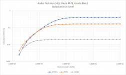
Thank you for these, jackinnj - the method looks very plausible and I don't see a flaw so seems real to me.Just one more, I popped out the Grado Blue1 from my nieces setup -- high DCR and low inductance:
Lots interesting to comment on, but the first is that different carts show different levels as to the turning point for deviation from ideal inductive behaviour.
As a first look, I'd guess this has to do with excitation flux becoming a greater percentage of total flux change with smaller signals. But that would be true for small flux changes where the source was the waggle of the generator too. It reminds me of what got me in to the concept of this loss mechanism a time back now, but your 3577a is a nice piece of kit to explore it with.
I'd venture that reciprocally, a cartridge as a generator would show the same profile, which being non-linear with level, would effectively behave as an expander?
LD
Can you verify the accuracy of the measurements below 1 mV? Maybe with a reference inductor? I would think noise etc. would be a limit at those low levels.
what confuses me is that the audio technica has a laminated core and the Shure does not. I would not have expected that result which seems to imply on first glance that Low-Z is best.
At first glance, I think this could be an excitation issue, a material property, rather than eddy current.what confuses me is that the audio technica has a laminated core and the Shure does not.
It's a HP3577A, check it out it's way cool. What makes you think a reference inductor, with a similar core material, wouldn't show the same issue?Can you verify the accuracy of the measurements below 1 mV? Maybe with a reference inductor? I would think noise etc. would be a limit at those low levels.
LD
Last edited:
Take a look at the permeability curves in this link:
Electrical Communication - Permalloys
Low inductance at low levels is possible, but this goes with a peak and then falling with saturation, there is no flat zone
Electrical Communication - Permalloys
Low inductance at low levels is possible, but this goes with a peak and then falling with saturation, there is no flat zone
Demian, will do tomorrow. As always your advise is most appreciated.
HP3577 is a wonderful instrument -- state of the art in 1984 with dynamic range of 100dB, but as the upper freq was less than 200kHz for these measurements I used the AP. You can buy an HP3577a with the S-parameter test set for a few hundred dollars in the US.
HP3577 is a wonderful instrument -- state of the art in 1984 with dynamic range of 100dB, but as the upper freq was less than 200kHz for these measurements I used the AP. You can buy an HP3577a with the S-parameter test set for a few hundred dollars in the US.
Ahh! OK.Good but in there lies anything that is due to (master disk cut) + (transfer to stampers) + (vinyl pressing) + (vinyl playback) and you can not discriminate between all these.
George
Regards
I have used the 3577. However signals below 1 mV mean a lower SNR. The lower SNR can compromise the accuracy. Perhaps a capacitor with a similar reactance would be a valid test. What the plot shows is the reactance diminishing as the signal goes down, and at about the same rate for several cartridges. That seems quite backwards.
Magnetic materials with hysteresis, like some Permalloy types show reduced mu at low levels, not very desirable in a cartridge....What the plot shows is the reactance diminishing as the signal goes down, and at about the same rate for several cartridges. That seems quite backwards.
Another way to see what happens at low levels would be to measure the change in self resonance with level. This should be less noise sensitive since you are looking a peak amplitude.
That's how the hypothesis that inductance is level sensitive for small signals started. An observation that cartridge LCR resonant f apparently correlates inversely with test track level, and a subsequent attempt to reconcile results.Another way to see what happens at low levels would be to measure the change in self resonance with level.
And the 3577A is well capable of measurements at hand.
LD
Last edited:
I should add, it's not that the LCR resonance is of concern. Rather, that effects might be reciprocal and so affect output of the generator at small signal levels.That's how the hypothesis that inductance is level sensitive for small signals started. An observation that cartridge LCR resonant f apparently correlates inversely with test track level, and a subsequent attempt to reconcile results.
One might hypothesise a level sensitive f response, for example......or a non-linear amplitude response, such as expansion...…….
LD
If it were an air-core we wouldn't have to worry about the B's and H's.
The HP3577 takes a long time to resolve and the averaging methodology is not ideal for this type of measurement. Since I am looking at the impedance at 10kHz and 10Hz I decided to switch to the AP and use 2-channel measurement with 300 ohm input impedance.
The HP3577 takes a long time to resolve and the averaging methodology is not ideal for this type of measurement. Since I am looking at the impedance at 10kHz and 10Hz I decided to switch to the AP and use 2-channel measurement with 300 ohm input impedance.
Attachments
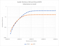
Just an academic exercise -- inductance vs excitation level for the Shure M78 and Audio Technica AT4540ML at 10kHz, 10uV to 100mV (not a lot of useful info until 30uV):
How do you explain the fact that the current noise of a high Ib bi-polar op-amp easily shows the LRC resonance of the coil as specified on the cartridge data sheet? I've measured it and posted the pics here years ago. The op-amp was Ib comped so we're talking nV of excitation. Same was true of the self noise as measured with a FET op-amp.
Last edited:
One might hypothesise a level sensitive f response, for example......or a non-linear amplitude response, such as expansion...…….
LD

-RNM
That C is somehow not what it seems to be ?How do you explain the fact that the current noise of a high Ib bi-polar op-amp easily shows the LRC resonance of the coil as specified on the cartridge data sheet? I've measured it and posted the pics here years ago. The op-amp was Ib comped so we're talking nV of excitation. Same was true of the self noise as measured with a FET op-amp.
LD
2nd edit: here's a blast from the past for tonearm resonances calculated impedance
LD
If the arm is typical hollow tube .... you can dampen these with little to no other side effects 🙂 By injecting expanding foam sealant inside the arm tube. yes, same as used in insulation. large cell/small cell/density can be obtained. Very light weight evenly distributed end to end.
Amazing affect on sound. smoother, not so rough sounding. IIRC.
THx-RNMarsh
- Status
- Not open for further replies.
- Home
- Source & Line
- Analogue Source
- Cartridge dynamic behaviour