AKG P8ES impedance
George
George
Attachments
-
 1 Photo.JPG922.4 KB · Views: 364
 -
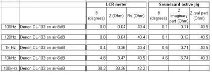
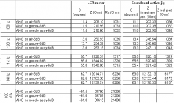 8 comparison btn LCR meter and soundcard readings.PNG24.3 KB · Views: 110
 -
 7 AKG real & imaginary parts of impedance-60dB level.PNG67.3 KB · Views: 108
 -
 6 AKG real & imaginary parts of impedance-6dB level.PNG55.8 KB · Views: 110
 -
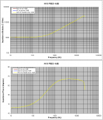
 5 AKG impedance-60dB level.PNG64.9 KB · Views: 331
 -
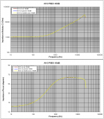
 4 AKG impedance-6dB level.PNG64.2 KB · Views: 334
 -
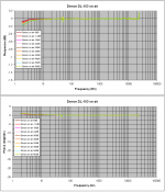
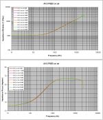 3 AKG on air impedance all signal levels.PNG61.9 KB · Views: 339
 -
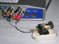
 2 measuring jig.PNG67.1 KB · Views: 338
George: Some great measurements, thank you. Particularly the measurement with no stylus assembly present just to prove the point 🙂
Thank you Bill.🙂
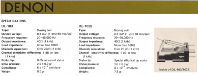
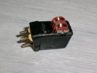
This is the last cartridge in the series.
DL-103 with broken cantilever.
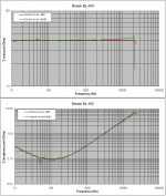
Response test
George
This is the last cartridge in the series.
DL-103 with broken cantilever.
Response test
George
Attachments

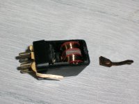
DL-103 with broken cantilever.
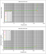
Impedance test
George
Impedance test
George
Attachments

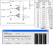
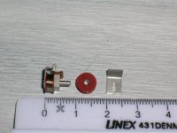
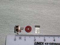
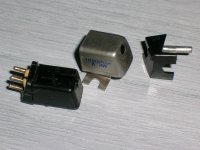
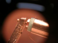
I dissected the body of the Stanton and took a few dimensional measurements with a caliper.
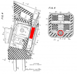
In one of Walter Stanton’s patent (US 3297831) my Stanton MK V is described in detail . So using the sectional drawing and the measurements, I have a rough idea of the magnetic motor structure.
Coil Outer diameter: 6.16mm
Coil inner diameter: 2.08mm
Coil height: 1.88mm
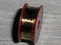
Wire diameter: 0.04mm
Coil turns ~2500
Magnetic path length :0.0176m
Magnetic core cross section: 0.0000016376sq.m
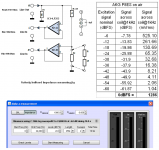
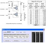
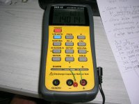
I altered the impedance measuring jig (replaced the 1kOhm ref resistor with a 9.945Ohm resistor).
I used 120Hz signal with different amplitude settings and took some wav recordings. I converted those to txt using Audacity and had it entered in Excel.
R ch represents coil’s voltage.
((L ch) – (R ch))/Rref is the coil’s current.
I calculated the magnetization field H (A/m) and magnetic flux B (T).
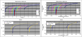
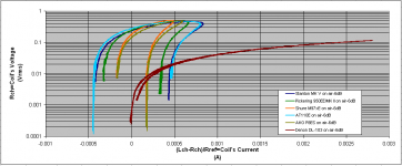
As B is analogous to coil’s voltage and H is analogous to coil’s current, the coil’s voltage against coil’s current diagram is of the same shape with the B against H diagram. Therefore one can deduce the shape of magnetic hysteresis curve by looking at the shape of coil’s voltage-coil’s current curve
So I had a look on all my cartridges
It seems all magnetic cores to be on the same range of magnetic hardness (same retentivity), except from the Denon which has the magnetically softest core.
They all differ in coersive force, thus they differ in hysteresis losses.
Again the Denon has by far the smallest hysteresis losses, then AKG and Shure, then Pickering and the higher losses are on the AT and Stanton.
George
In one of Walter Stanton’s patent (US 3297831) my Stanton MK V is described in detail . So using the sectional drawing and the measurements, I have a rough idea of the magnetic motor structure.
Coil Outer diameter: 6.16mm
Coil inner diameter: 2.08mm
Coil height: 1.88mm
Wire diameter: 0.04mm
Coil turns ~2500
Magnetic path length :0.0176m
Magnetic core cross section: 0.0000016376sq.m
I altered the impedance measuring jig (replaced the 1kOhm ref resistor with a 9.945Ohm resistor).
I used 120Hz signal with different amplitude settings and took some wav recordings. I converted those to txt using Audacity and had it entered in Excel.
R ch represents coil’s voltage.
((L ch) – (R ch))/Rref is the coil’s current.
I calculated the magnetization field H (A/m) and magnetic flux B (T).
As B is analogous to coil’s voltage and H is analogous to coil’s current, the coil’s voltage against coil’s current diagram is of the same shape with the B against H diagram. Therefore one can deduce the shape of magnetic hysteresis curve by looking at the shape of coil’s voltage-coil’s current curve
So I had a look on all my cartridges
It seems all magnetic cores to be on the same range of magnetic hardness (same retentivity), except from the Denon which has the magnetically softest core.
They all differ in coersive force, thus they differ in hysteresis losses.
Again the Denon has by far the smallest hysteresis losses, then AKG and Shure, then Pickering and the higher losses are on the AT and Stanton.
George
Attachments
George these are absolutely fascinating measurements, but I confess I really don't know how to interpret them. Re: the Denon given its much lower sensitivity are you measuring it at the same voltage levels as the MM carts? Have you tried measuring the Denon with a lower load resistance (eg 100R or 500R)?
Finally how do you interpret these results? That final set of hysteresis curves is particularly interesting. I am surprised by the much higher currents in the Denon. Is this somehing that is going to be typical of MC carts with low inductance and low coil R? Knowing that all of these are "good sounding" cartridges what are we to make of these results?
Finally how do you interpret these results? That final set of hysteresis curves is particularly interesting. I am surprised by the much higher currents in the Denon. Is this somehing that is going to be typical of MC carts with low inductance and low coil R? Knowing that all of these are "good sounding" cartridges what are we to make of these results?
Interesting. I'm also still trying to work out what it actually means. Great to have data though and thank you again George. I have a couple of Low-Z MMs (and resisting an EPC-205II-L). May have to post one to George to add to the data set.
Thank you nezbleu and Bill.
I don’t draw any conclusions yet, only the obvious technical aspects.
I guess, all important information is encoded into the impedance diagrams I posted some post above. The magnetic domain diagrams will surely reflect those information too (e.g. hysteresis diagram I am sure will widen up when the excitation signal increases in frequency, reflecting the resistive component of the complex impedance).
Why I do this analysis/ brake into pieces then? Only curiosity.
When I finish, some more info on which part of the motor causes what on the impedance curve will hopefully come out.
(Mr. Hyde needs to wave some motivation while Mr. Jekyll is suspiciously watching).
Now that I have the coils in an accessible stage, maybe Demian wants to suggest some test
George
Attachments


The signal current from a typical MC with 100R load can be much higher than a MM with 47k load.Re: the Denon given its much lower sensitivity are you measuring it at the same voltage levels as the MM carts? Have you tried measuring the Denon with a lower load resistance (eg 100R or 500R)?
The signal power of both types is similar, if anything MC slightly higher.
MM generators are fairly poor - too many turns of really fine wire
Now that I have the coils in an accessible stage, maybe Demian wants to suggest some test
George
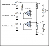
The question is whether you can emulate the stylus's magnetic motion. Trick one would be a small coil where the stylus would be. It would need to be oriented to have the correct interaction with the pole pieces. It should not have a magnetic core and I would drive it in a constant current mode- essentially a resistor in series. If the voltage across the resistor changes with frequency it would need to be compensated for since that would mean the flux would be changing.
Then my interest would be the level vs distortion and if the distortion changes with load. Conceptually as you load the coils more current pases through and the magnetic field from the current interacts with the magnetic structure.
This may be a bigger issue with a moving coil but it may define the distortion of the system.
The other issue would be the effects on frequency response of the coil with both skin effect (most likely very small) and the magnetic circuit.
Thank you Demian.
What I understand you suggest for a MM or a MI cartridge is, placing an excitation coil where the rear part of the cantilever would have been (in place of the moving magnet or of the moving iron) and monitoring the output of the L & R coils of the cartridge.
Is this correct?
George
What I understand you suggest for a MM or a MI cartridge is, placing an excitation coil where the rear part of the cantilever would have been (in place of the moving magnet or of the moving iron) and monitoring the output of the L & R coils of the cartridge.
Is this correct?
George
Attachments
Hi George,
I have a question from a different perspective.
I can see in your BH curves, that you go as far as letting 3mA flow through your MC Cart.
My question has to do with the switch on of a MC preamp.
For a short period of time, order of several milliseconds, an uncontrolled amount of current may flow into the Cart when using a Bipolar input circuit.
Have you any information, or even an idea how much current this may be as an upper limit ?
Hans
Hi Hans
I am not able to answer your question.
I think Scott will be able to tell simply by inspection when you show him a certain schematic.
Many can use the help of a simulator.
George
I am not able to answer your question.
I think Scott will be able to tell simply by inspection when you show him a certain schematic.
Many can use the help of a simulator.
George
Many can use the help of a simulator.
That's what I would try since ideal switches are components in all the simulators they can be sequenced to simulate all manner of sloppy plugging and unplugging. A shorted battery can supply amps, a small Li pack can start your car.
I think Hans is talking about the input transistor base bias current flowing through the cartridge when the circuit is powered on.
George
George
I think Hans is talking about the input transistor base bias current flowing through the cartridge when the circuit is powered on.
George
My question was in fact how much current an MC cart may handle for a short period of time. I can simulate quite well what the preamp does at at switch on, but how much current may maximally flow into the MC Cart as a ballpark figure.
Less than 1mA, less than 10 mA or what?
Depending on that figure, certain measures may have to be taken to limit this current to below this value at switch on.
Hans
I think Hans is talking about the input transistor base bias current flowing through the cartridge when the circuit is powered on.
George
If you sequence the supplies poorly enough you can get diode to cart to ground to smoke.
The Stanton I dismantled had SWG48 wire (1.6 mil diam). Engineering tables show this wire handle 3.4 to 5.2 mA DC continuously.
The coil of an MC is quite open to air with a few turns and very few layers (maybe single layer), so there should be no derating due to heat build up.
And I think the wire of the DL-103 is thicker than that of Stanton. I have to check it.
George
The coil of an MC is quite open to air with a few turns and very few layers (maybe single layer), so there should be no derating due to heat build up.
And I think the wire of the DL-103 is thicker than that of Stanton. I have to check it.
George
Attachments
- Status
- Not open for further replies.
- Home
- Source & Line
- Analogue Source
- Cartridge dynamic behaviour