The modification of the Midas with I2C will involve some skilled surgery, I hope you'll be able to do it.
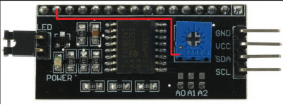
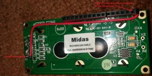
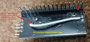
Coolmaster, please confirm 12C module modification reroute picture red line, as per 12C module schematic VR terminal pin 1 is ground, I will remove pot from PCB than terminal pin 1 for pot on board cut round bigger hole for pin 1 go free and solder wire VR pin 1 below PCB to connect VEE Midas pin 15 . Please confirm I'm on correct track?
Attachments
Coolmaster, please confirm 12C module modification reroute picture red line, as per 12C module schematic VR terminal pin 1 is ground, I will remove pot from PCB than terminal pin 1 for pot on board cut round bigger hole for pin 1 go free and solder wire VR pin 1 below PCB to connect VEE Midas pin 15. Please confirm I'm on correct track?
Yes, correct on your diagram. Please double triple check the pot pin 1 is completely isolated from the pcb ground plane, connect a wire from POT pin 1 to pin 15 (Vee assigned at Midas display). Also, at the side of the LCD, terminals A1 & K1 are to be open.
Attachments
Last edited:
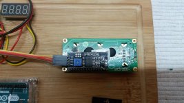
Yes, open. My picture show a fully working unit after the mod. Jumper of the I2C module also removed.
Last edited:
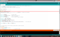
Today I have modified 12C module for Midas as per your instruction. Removed pot and isolate ground from PCB reroute pot pin to LCP pin 15, jumper removed and A1&K1 track opened. After all connect Arduino UNO to LCD Midas and PC LCD not turn on back light still dark, even 12C module power LED not on. Another problem. Existing "Tach" program file I have added below code for Midas, but not able load there is error find attached screen shot
#include <Wire.h>
#include <LiquidCrystal_I2C.h>
LiquidCrystal_I2C lcd(0x27, 2, 1, 0, 4, 5, 6, 7, 3, POSITIVE); //* Midas LCD I2C enabled
I have doubt, if we open A1&K1 BL will not work? need your advise. Thanks
#include <Wire.h>
#include <LiquidCrystal_I2C.h>
LiquidCrystal_I2C lcd(0x27, 2, 1, 0, 4, 5, 6, 7, 3, POSITIVE); //* Midas LCD I2C enabled
I have doubt, if we open A1&K1 BL will not work? need your advise. Thanks
Attachments

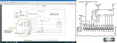
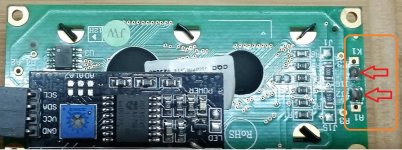
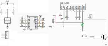
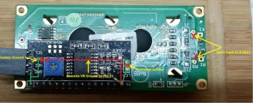
I think we have missed out something, Midas display as per your instruction I have open track to A1 & K1 see the picture red marked. Seems your Midas display I did't see you open A1&k1. I have another doubt VR ground reroute to LCD pin 15 Vee, do we need to isolate Vee Pin 15 from PCB or just over connect . I have over connect Vee Pin 15 from VR ground. Check 12C drawing X green mark need open? Thanks Raj
Attachments
Last edited:
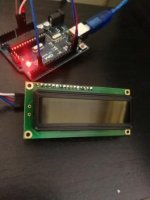
Hi Coolmaster are you there? I have update my picture what I have done modification. Please to be note VR pin 3 is the connected ground not pin1, same i was isolate VR ground pin 3 reroute to LCD header pin 15, power jumper removed. A1&k1 PCB track opened. when I connect 12C to Arduino, when I look closely (hard to see) LCD uppercase can see "Transparent block" seems LCD back light not "ON". Further I need your support.
Attachments
Rajkumar-
I don't have this display, but I've worked on dozens of LCD displays from numerous mfrs. From Coolmaster's diagrams, it appears he connected the two ends of the contrast pot between Vcc (+5VDC) and a negative supply instead of Vcc and ground; this allows the wiper of the arm to provide a (potentially) negative drive level to the display, depending on the wiper position. This is usually only needed if the display is designed for extended temperature operation. I don't see on your diagrams where there is any negative supply (-Vee) to connect to? The low side of the pot MUST be connected to either ground or a negative supply or you will not be able to set the contrast to a visible level.
Have you tried using the display as it was set from the factory? I think I would return the connections to the factory settings and modify it only if it does not produce the results you want.
As far as the back light, pins 15 and 16 should be connected to the display 'A1' & 'K1' from the factory, which allows operation of the back light without having to provide a separate connector or wires. If you cut the traces at A1 & K1, I don't see how it could function. Check with the data sheet for the display; it may need an external dropping resistor to limit the current going to the LED backlight when powered from 5VDC.
Last edited:
Hi Bill, yes you're right, as per instruction from coolmaster A1 & K1 need to open, if open LED BL will not work. pot pin 1 5V pot pin 3 ground, pot pin 3 reroute to LCD pin 15 VEE, please note existing Vee pin 15 have 5V from jumper, jumber removed, now Vee PIN 15 receive 5V from rerouted through Pot pin 3. Now I suspect problem opened A1&K1 need to connect back and check. I have tried Original Midas display connect to 12C module and I found LCD U3 chip get very hot, if I leave connect may fried chip. I am out of home, this weekend I will try connect A1&K1 let see. I am mechanical engineer and I am working not Arduino and LCD first time. Thanks
Attachments
I downloaded the data sheet for the Midas MC21605G12W-VNMLG and pin 15 is -Vee not LED +. You must make sure pin 15 on the I2C board is not connected to anything; it most likely is connected to VCC possibly through the "LED" Jumper. Verify that pin 15 is a negative voltage when everything is connected; the Midas data sheet does not give a spec for this. It could be -2V to -5V, but it should be negative. With pin 15 connected to the low side of the pot, confirm with a voltmeter that the wiper of the pot goes from the negative voltage at pin 15 to +5V (VCC).
LED Backlight: The cathode (K1 on LCD board) should be left connected, do not cut the trace on the LCD board. Confirm that A1 on the LCD board is not connected to pin 15; you may have to cut the trace on the LCD board to accomplish this. A1 will need 5VDC for the backlight to work. Check with an Ohmmeter if A1 is connected to VCC (pin 2 on the interface); if it is, the LED back light should work. If not, you will need to supply 5VDC to A1. The I2C "LED" jumper may have Vcc on one of the pins; confirm this with an Ohmmeter (with power off). Connect a wire jumper from this VCC point to A1 on the LCD board.
LED Backlight: The cathode (K1 on LCD board) should be left connected, do not cut the trace on the LCD board. Confirm that A1 on the LCD board is not connected to pin 15; you may have to cut the trace on the LCD board to accomplish this. A1 will need 5VDC for the backlight to work. Check with an Ohmmeter if A1 is connected to VCC (pin 2 on the interface); if it is, the LED back light should work. If not, you will need to supply 5VDC to A1. The I2C "LED" jumper may have Vcc on one of the pins; confirm this with an Ohmmeter (with power off). Connect a wire jumper from this VCC point to A1 on the LCD board.
Thanks Bill, I will check it tonight when reach home, can look back my post 20th January 2019, 04:38 PM file loading error "liquidcrystal_12C.h" not in directory? I need to download library and add to the library can solve this error? is it correct?
Use the library menu in the Arduino IDE and see if you have it and it is located in the right directory. You can download and install if needed.
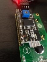
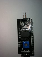
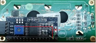
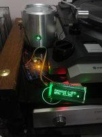
Hi Bill, Happy news I have successfully converted "Midas MC21605G12W and 12C interface module. On 12C module modification VR Pot need to completely removed from PCB then, pot PIN 3 hole on PCB need to drilled bigger hole, for pin without contacting PCB and solder wire pot pin 3 and reroute to VEE Pin 15. Jumper pin need to be remove from PCB by de-solder. Please note Jumper one end have 5V another end connected to PIN 15, Pot pin 3 reroute connected to one end of jumper which one already connected to PIN 15. Regarding to LCD display code for Midas I have not done anything, I have used existing standard LCD code. Didn't change any letters, still working good without any issue. I have attached picture of 12C & Midas modification with help who other who need to convert. I will post once compete with case. Thanks once again Bill & Coolmaster. Rajkumar
Attachments

Last edited:
Hi Bill, need your help my turntable tachometer I used cheap "Hall Effect Sensor module using M44 switch" after few days, signal LED not on but still work, I have noticed my Arduino R3 regulator chip get very hot when connect Hall Effect Sensor Module. I found in eBay "Phoenix Engineering rs-3345 Tachometer Sensor" this sensor will work on Arduino Uno R3? Thanks Raj
Attachments
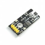
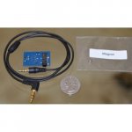
The sensor should not draw that much power. The sensor from Hi-Fi Heaven will work.
You can also buy them from SOTA or you can make your own:
OSH Park ~
You can also buy them from SOTA or you can make your own:
OSH Park ~
At OSH available PCB how about other parts AH337 sensor, zeners resistor order from other source? OSH available diy kit? Can I order those parts from Mouser. Please give advise. Thanks
Hi Bill, better I order Hifi Heaven, some of the parts Zener and resistor not available in Mouser back order, also parts + shipping cost close to eBay price. So I have additional cable + magnet from Hifi-heaven. Thanks lot Raj
- Home
- Source & Line
- Analogue Source
- Digital Tachometer for record player (LCD display)