Condolences for your expensive loss, sincerely.
Many years ago, building a special 6x15 panoramic film camera for my work, I learned my lesson: I sent all the pieces to black anodizing, and then started to epoxy them together. Some detached without any warning. The anodiser explained that to make them shiny and durable they were Teflonized at the end of the process.
So use a bit of sand paper to find a moderately rough aluminum surface in the areas to be glued. It's not a matter of resin, usually, but of surfaces.
hope this helps - carlo
Thanks everybody for your helps!
I went to Home Depot and bought a JB steel reinforced epoxy. I tried a small portion. It seems to me it is pretty good. For the parts of head shell, I made it myself, but this time, I am going to let someone who has all the equipments do it for me. So, the head shell will fit the bushing nicely and gets maximum contact area. I will also sand the contact area of the air bushing. Hopefully, all of this will solve the problem.
Jim
Hi jim. before sanding put a little drop of resin on the bushing and let it cure; then try to take away witn a stick. Black anodization is often hard anodization, that is with the pores well sealed and very slick, but not always with teflon. Acetone rinsing may be enough.
One of the strongest resin in my experience is UHU plus 24h - transparent (no fillers- no solvents). more speed = less resistance
ciao - carlo
One of the strongest resin in my experience is UHU plus 24h - transparent (no fillers- no solvents). more speed = less resistance
ciao - carlo
Last edited:
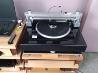
I finally get one of my air bearing arms fixed and up running.

This is the damping device. I designed the damping device with an emphasis on vertical damping.

This time I completely redesigned the arm and have a machinist made the parts for me. The total mass of the arm is 102 grams. Usually, I won’t run a medium compliance cartridge on a heavy arm, but I have no choice. The cartridge I fitted on this arm is Ortofon A90, a medium compliance cartridge. I did an eccentricity test. From the video, it seems to me it runs very nicely. Please see the video.
YouTube
This is the damping device. I designed the damping device with an emphasis on vertical damping.
This time I completely redesigned the arm and have a machinist made the parts for me. The total mass of the arm is 102 grams. Usually, I won’t run a medium compliance cartridge on a heavy arm, but I have no choice. The cartridge I fitted on this arm is Ortofon A90, a medium compliance cartridge. I did an eccentricity test. From the video, it seems to me it runs very nicely. Please see the video.
YouTube
Hi Warrjon,
I know. It is pain to have a compressor to be set in your home. If you can make a Niffy's style arm, I believe, it will be on a par with air bearing arm. The only difference I guess may be in the bass area. A mechanical linear arm can only allow very limited total mass. Heavy mass will enhance bass performance. Another difference may be background noise. My newly designed arm is extremely quiet. It surprised me as well.
I know. It is pain to have a compressor to be set in your home. If you can make a Niffy's style arm, I believe, it will be on a par with air bearing arm. The only difference I guess may be in the bass area. A mechanical linear arm can only allow very limited total mass. Heavy mass will enhance bass performance. Another difference may be background noise. My newly designed arm is extremely quiet. It surprised me as well.
I have built Niffy style arm but it's on a bridge mounted both sides of the TT. Carriage weight is 52g with cartridge, my Stanton 881s is very high compliance
It is very good. Bass is way better than any pivoting arm I have had and it's much quieter less clicks and pops. I'll never go back to a pivoting arm after hearing this. Even my first prototype with overhead glass rods was as good as my EPA100 but with better bass.
It is very good. Bass is way better than any pivoting arm I have had and it's much quieter less clicks and pops. I'll never go back to a pivoting arm after hearing this. Even my first prototype with overhead glass rods was as good as my EPA100 but with better bass.
Attachments
Hi Niffy,
I thought 102 grams might be too heavy for medium compliance cartridge such as A90. However, it looks A90 works just fine. Ortofon's cartridges have a very balanced sound. It can be boring sometimes for some people. But once you listen to it more and more, you may find nothing is missing.
Jim
I thought 102 grams might be too heavy for medium compliance cartridge such as A90. However, it looks A90 works just fine. Ortofon's cartridges have a very balanced sound. It can be boring sometimes for some people. But once you listen to it more and more, you may find nothing is missing.
Jim
But once you listen to it more and more, you may find nothing is missing.
Jim
Except for some colouration. The best cartridge I ever owned was the ortofon mc3000 from 30yrs ago that used much of the technology now used in the A90. I loved that cartridge.
Niffy
Hi Carlo,
Contrary to popular belief vertical damping is more crucial than lateral with a linear arm. This is dispite lateral mass being higher. It is also true for conventional pivoted arms except to an even greater extent. One of the difficulties in developing a linear arm is getting the balance of vertical and lateral damping just right. I think Jim has put quite a lot of effort into this.
Incase you haven't seen it this thread goes into quite a bit of detail as to how the difference in the resonance and damping of the arm effects speed stability.
Turntable speed stabilty
Niffy
Hi Carlo,
Yes. I emphasize vertical damping in my design. First, I used a piece of plastic as the material for the paddle. So, it will increase the buoyancy force. The shape of the paddle is designed to fully utilize the buoyancy force, too. Although I don't have the theory of why vertical damping is more important, in my opinion, there is a relationship between vertical damping and lateral inertia. In other words, I think, vertical damping can damp the arm both vertically and laterally. For the linear arms in the market, the designers still take conventional ways to design the damping device, such as Kuzma airline and Walker Audio Proscenium.
Jim
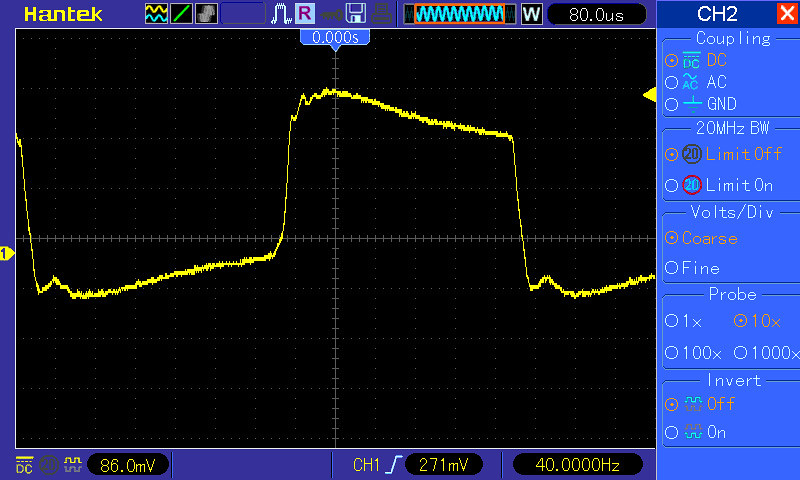
I also did some tests today. I am pretty happy with most of results except square wave test for right channel. Please see yellow square wave test below. The test shows it missed upper left corner a bit.
Square wave test left channel.

Square wave test right channel.
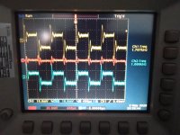
Left channel tone-burst tests at different frequencies.


Right channel tone-burst tests at different frequencies.


Square wave test left channel.
Square wave test right channel.
Left channel tone-burst tests at different frequencies.
Right channel tone-burst tests at different frequencies.
Hi Niffy. remembering well your and Jim's posts on the need for damping on the LTs, especially for the air bearing ones, I had noticed the particular shape of the antidamping, clearly derived from precise choices and experiences. It was just the curiosity to know if I had understood correctly how it worked.
My personal belief about damping in pivoted ones is that it looks like the antiskating device: if improperly designed, set up, and maintained, brings more damage than improvements*. So better without, even on my last unipivot - but it took me 3 different projects and many mods to dimension the masses in order to avoid it. Not to mention the time wasted to design a decent antiskating.
About LTs I have no opinion - experience: the Lil Casey does not seem to need it (maybe i think so, because it would not be easy at all to insert it)
Thanks for the explanation Jim. What interests me more of tonearms is always to understand how they work, and why.
Again, congratulations: the graphs confirm the excellent behavior seen in your video.
carlo
* eg - think about the unwanted, unpredictable role of the cables on both these aspects
Last edited:
Hi Jim,
The first thing I notice in the square wave test is you are using 10x probe on CH1 but CH2 looks to be 1x. The rise time looks to be about the same, but the frequency is different???. Was this with the phono-pre connected to the preamp or did you disconnect the phono-pre.
Try performing the test again using 1x probes on both channels this will still give you 1M input impedance. Leave the phono-pre connected to the preamp or use a load resistor with same input Z as preamp and measure across the resistor.
Hi Warrjon,
I did the tests again. This time I make sure that both probes at 1x and turned the channel menus on. I didn’t use a preamp in the tests. The oscilloscope was directly connected to the outputs of the phono. The results don’t seem to have a big difference comparing with previous tests. Both upper left corners and lower left corners are cut off for right channel, CH1. The test for the left channel, i.e., CH2 looks very good.
Right Channel, CH1

Left Channel, CH2

Jim
I did the tests again. This time I make sure that both probes at 1x and turned the channel menus on. I didn’t use a preamp in the tests. The oscilloscope was directly connected to the outputs of the phono. The results don’t seem to have a big difference comparing with previous tests. Both upper left corners and lower left corners are cut off for right channel, CH1. The test for the left channel, i.e., CH2 looks very good.
Right Channel, CH1
Left Channel, CH2
Jim
Just trying to eliminate variables.
Why is CH1 inverted from CH2 are you triggering on the same CH for both measurements?
Next I would swap the input to the phono pre to enure it's not the phono causing the difference. This could be caused by capacitive loading difference between the channels. If it does not change then I would swap the leads at the turntable end.
Hi Warrjon,
Here are the test results with swapping the inputs on the phono. You can see the slight imperfection tracking moves to CH2. It indicates that the imperfection of tracking is embedded in the cartridge itself. For the arm itself, there is no reason to believe the same arm can track the left channel and the right channel differently.


Jim
Here are the test results with swapping the inputs on the phono. You can see the slight imperfection tracking moves to CH2. It indicates that the imperfection of tracking is embedded in the cartridge itself. For the arm itself, there is no reason to believe the same arm can track the left channel and the right channel differently.
Jim
Hi Jim,
Have you tried adjusting the arm rail level while playing the squarewave, to see if this has an effect on the LCH. It's almost like the stylus may have better contact with RH side groove????
The LCH trace indicates a roll off of high frequencies. Both CH's show a low frequency roll off but this could be an artifact of the RIAA.
You inspired me to test my setup. Here is my LTA with a Stanton 881s tracking the CBS STR112 1kHz band 1A. This LP has a slight warp that my clamp does not completely flatten which is why the difference in L and R CH frequency.
This is with no loading except the scope input so the load C is a bit too low at 33pf (270pf needed) which is why the ringing is a bit large. The red trace is the math function CH1 - CH2 channel difference.
Attachments
- Home
- Source & Line
- Analogue Source
- DIY Air Bearing Linear Arm