
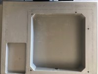
The skirting board made 3 layers of 40 millimeters from plywood with the necessary cutouts on the machine. Then gluing and putty
painting in the chamber, chose a matte color.
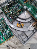
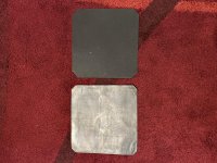
For weight, I used a plate of about 7 kg. Total weight without motor 27 kg.
The motor was mounted on long studs, dense rubber on both sides. The studs do not touch the baseboard.
painting in the chamber, chose a matte color.
For weight, I used a plate of about 7 kg. Total weight without motor 27 kg.
The motor was mounted on long studs, dense rubber on both sides. The studs do not touch the baseboard.
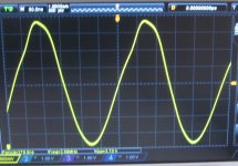
My reasoning was simple. More accurate and stable quartz will be at least no worse ... I abandoned the neon strobe in favor of diodes.
There is a free line for power in the socket. I applied 9 volts there.
Using the 140v line is a great idea, I use it myself for an extra 32.5v supply fed in thru the power lead which means the control and drive pcb no longer share a supply.
Can you comment on any audible improvements using the modern quartz updating ?
if purely mathematically, stability improvement is about 0.0056
How did you determine this figure? Are you saying the stability theoretically improves by 0.0056 *percent* with the new oscillator? There's no unit there.
Do you have details on the oscillator you used?
I doubt it will make a meaningful difference, given the application (and the circuit topology), as @JP pointed out... but if you're able to measure a difference in speed stability, I will eat my words.
If you're hungry for tweaks under the hood, I would start by recapping the drive unit and refurbishing (and re-calibrating) the power supply... I still see original capacitors in your pics of the drive unit.
It worked
I fretted over the mounting bolt holes a lot. Didn't want to mess up my plinth.
This weekend I marked and drilled the holes. It worked perfectly so here are my thoughts and what I did in case it helps anybody in the future.
First, use any method you want as long as you can do it precisely. This is what I did.
1. Use a sharp pencil.
2. I placed the SP-10 in the plinth and positioned it where I wanted and drew a line around it.
3. I bottomed out the mounting screws in the chassis, and used a micrometer to measure their position. Digital readout and very accurate. Ad or subtract for the bolt radius to get the exact center and mark it on the plinth. I had tried a template and was not happy with the accuracy I had. Probably me. It might work perfectly for you.
4. Use whatever drill you can get your hands on that you can center exactly on the position and not travel when you start to drill. I only used that drill for the start position to take the first drill.
5. I used 4 drills per hole The position drill. A 5.5mm double procession coated drill that would get me 2/3 of the way through. A 1/4in dia long jobber drill that would get me to the other side. And finally a 7.5mm drill from both sides for the final hole size. (The size Bon had suggested). I used a high quality portable drill jig that worked really well and I had very little wander.
I think I worry too much but I don't want to start over at this point.
I am now down to the finishing touches, paint and the EPA100 mounting hole.
Don
Attachments
Now you are getting close to mounting the mk2, before you close everything up, you might consider this tweak. To support the plinth ability as a sink for unwanted micro vibration, by padding the gap between the bearing cap and the plinth with a combination of lead sheet/flashing and barium loaded vinyl sheet. The vinyl will allow some compliance when CAREFULLY snugging down the plinth bolts. The idea is to better damp any ball/thrustpad noise by contact with the plinth mass. Care need to be taken to get just the barest amount of pressure on the bearing cap. The thin rubber membrane covering the bearing will also provide some compliance. I haven’t measured the effectiveness, but it seemed to do no harm. Warrjon has taken the principle further with a bearing brace in the Kaneta style plinth.I am now down to the finishing touches, paint and the EPA100 mounting hole.
Don
Attachments
Last edited:
warrjon,
A couple of questions (I may have lost track):
How is your bearing project coming? Did the vesconite work as expected?
Are you done with your TT experiments and testing or are you still working on it behind the scenes.
Thanks,
Don
Hi Don,
Not done any more on the Vesconite bearing as yet I have been sidetracked building a tonearm. I am thinking the EPA100 is now the weak link so decided to build a no compromise tonearm.
Ah lead, the magic material.
Lead against aluminum allows over 90% transfer of vibration energy and less then 6% reflected energy. Don't know about the resin/bento as I have no idea what its acoustic impedance is. But every metal I have run through the calculator shows over 90% energy transfer.
Lead against aluminum allows over 90% transfer of vibration energy and less then 6% reflected energy. Don't know about the resin/bento as I have no idea what its acoustic impedance is. But every metal I have run through the calculator shows over 90% energy transfer.
The upgraded oscillator is unlikely to make any difference. The reference signal is divided down quite a lot before it's actually used.
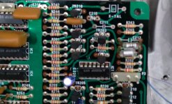
Re-capping the electronics is a waste of time, all caps on the electronic PBC's except C2, 4 & 6 on the Drive PCB are bypass for the electronics and will in all likelihood be good.
The PS by will need new electrolytic caps if it has not been done.
Re-capping the electronics is a waste of time, all caps on the electronic PBC's except C2, 4 & 6 on the Drive PCB are bypass for the electronics and will in all likelihood be good.
The PS by will need new electrolytic caps if it has not been done.
Hi everyone!
Hope i did not interfere with the current topic in this thread.
I am about to start rebuilding my 2nd SP10 MK2, and i need some advice from the Gurus here. Sometime back while i was restoring my first set, i hung the naked SP10 chassis for painting, and i accidentally knock it, it rang like a bell for a long time, this is no good!
So i was thinking to do the following:
1) To fill and flood the cavities behind the chassis with silicon for the purpose of hoping to damp the chassis further. Then put it back into a new plinth, most likely using 5 pieces of 1/2 inch plywood sandwich together.
2) To remove the motor from the Sp10 chassis, and mount only the motor to the new plywood plinth.
Both methods above allow me to use my 12 inch arm, whereas it obstruct the top cover when i mount it on the original Technics plinth.
Let hear it from the experts. Thank!
- Home
- Source & Line
- Analogue Source
- The Incredible Technics SP-10 Thread