As promised I have created another thread to discuss my latest foray into the land of phono stage design. I will admit to taking a short cut and rebuilding the Mini into the Mini II.
The major tradeoff is a reduction of gain on the order of 6dB perhaps more, the major benefit is the elimination of a critical capacitor in the original mini design.
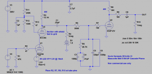
I confess that I have not yet traced the 6N14Ps in my possession and in fact designed the new front end referring to the various 6N14P parametric charts found on the net. I then tweaked things on the bench, but it is a relatively simple front end design.
Note that the ECC84, PCC84 and 6CW7 should all work in this front end as well. No current substitute for the 6S3P however.
I have just now simulated the circuit performance in spice using a commonly available model for the ECC84 which on the gain front might be just a bit optimistic.
The predicted gain is 48dB which I expect is not realized in practice (I need to measure it).
RIAA conformance in this particular pre measured as +0.2dB, -0.0dB.
Distortion as in the Mini is primarily determined by the second stage and due the reduction in overall front end gain is better than -70dBr @ 5mVrms input @ 1kHz.
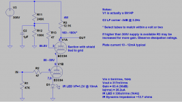
The cascode is bias at ~10mA, with fixed bias derived from an IR led having a VF of 1.2V and dynamic impedance of a couple of ohms. The upper cascode is referenced to a resistive voltage divider, one per channel and is ~87V.
I have a lot of catching up, I will post traces and models to the spice model thread when I have them. Another member has mailed me a number of ECC84 and PCC84 which I will measure and compare to the 6N14P I am using.
Noise performance turned out to not be a concern despite my previous worries about this issue.
More measurements to follow as I have time.
I'm listening to it as I write this post.
The major tradeoff is a reduction of gain on the order of 6dB perhaps more, the major benefit is the elimination of a critical capacitor in the original mini design.
I confess that I have not yet traced the 6N14Ps in my possession and in fact designed the new front end referring to the various 6N14P parametric charts found on the net. I then tweaked things on the bench, but it is a relatively simple front end design.
Note that the ECC84, PCC84 and 6CW7 should all work in this front end as well. No current substitute for the 6S3P however.
I have just now simulated the circuit performance in spice using a commonly available model for the ECC84 which on the gain front might be just a bit optimistic.
The predicted gain is 48dB which I expect is not realized in practice (I need to measure it).
RIAA conformance in this particular pre measured as +0.2dB, -0.0dB.
Distortion as in the Mini is primarily determined by the second stage and due the reduction in overall front end gain is better than -70dBr @ 5mVrms input @ 1kHz.
The cascode is bias at ~10mA, with fixed bias derived from an IR led having a VF of 1.2V and dynamic impedance of a couple of ohms. The upper cascode is referenced to a resistive voltage divider, one per channel and is ~87V.
I have a lot of catching up, I will post traces and models to the spice model thread when I have them. Another member has mailed me a number of ECC84 and PCC84 which I will measure and compare to the 6N14P I am using.
Noise performance turned out to not be a concern despite my previous worries about this issue.
More measurements to follow as I have time.
I'm listening to it as I write this post.
Attachments
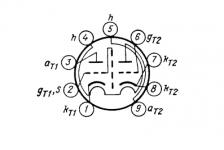
A few details about the 6N14P; I am particularly concerned about the placement of the grid pin (6) of triode 2 next to the filament pin (5) as this the point with lowest signal level in the entire tube. Probably not a bad idea to choose a low leakage socket material like ceramic or teflon for this application..
Special care is required for the filament supply if using this tube - I recommend extremely well filtered and regulated DC to heat the filaments for this reason.
Tie both cathode pins (7,8) together on triode 2 and connect directly to the IR led..
The tube does not seem particularly prone to oscillation if some minimal precautions are observed as noted in the schematic.
Attachments
Hi Piano3,
This is actually a great question... Note that the grid and shield are both very close to AC ground in my implementation of the cascode configuration, and from a DC perspective the shield is at close to the same potential as the plate in the lower half of the cascode, and roughly half the plate potential of the upper half of the cascode - from a DC leakage standpoint this is as close to ideal as it gets. The shield actually prevents the plates of the two sections from coupling capacitively which is not a big deal for an audio cascode, but is a problem with RF ones, in any event it cannot hurt.
This tube of course was not designed for audio applications, and the location of the most sensitive node - the grid at pin 6 is far from optimum as coupling from filament pin 5 can occur both by leakage across the socket and through capacitance.
In the distortion and noise FFT I did yesterday I observed a considerable peak at 120Hz, and while I do not know for sure I strongly suspect the filament supply is the culprit. I purchased a regulator off of eBay using a fairly high performance LT regulator (5 pin device I currently can't remember) and have measured the ripple at the output > 6mV which is fairly poor performance. (The seller of course claims ridiculously low output noise, which in practice is not realized) I suspect the PCB layout is to blame (dremel time?) and I probably need to build something from scratch to do the job - if that proves to be the case I will post it here.
Have you ever considered using what everyone is calling a capacitance multiplier for the heater supply? Digikey stocks a very high hfe transistor, 2SC4495, (50V, 3A) which would make a excellent emitter follower without having to use a Darlington. You could even supply the Zener from a CCS. I would think that noise could be made arbitrarily low.
Of Cap Multipliers and Noisy Computers
Funny you ask about the capacitance multiplier - I'm actually not a big fan of the approach, spent a good deal of my professional life working on, fixing and designing VIs for semiconductor ATE so I like an active solution, cap multipliers seem like a brute force solution to me.
Now I have had yet another epiphany relating to my computer based measurement hardware, and if I said a dead computer is a good computer when it comes to coexisting with analog hardware I would not be understating the situation. Even turned off the evil thing is radiating across the RF spectrum so I finally just unplugged it.
It seems I need to investigate getting a lower EMI computer as it is really messing up everything I try to do whether it is in use or not.
So there was no issue with 120Hz ripple on the filament supply, it is indeed down in the uV region as claimed, and the high voltage regulators broadband are under 400uVpp as well. (Ripple is much lower)
Some statistics
Ok given that I have given up on the FFT I did a few measurements the old fashioned way..
I measured a gain of +46dB relative to the input @ 1kHz which as I surmised proved to be a couple of dB lower than the prediction.
The gain of the cascode was measured as 63.4 or almost exactly 36dB (that should sound like a familiar number )
)
Channel to channel match at 1kHz was about as close to perfect as I have ever seen at better than 0.05dB in fact.
Overall gain compared to the pentode version is approximately 6dB lower, FFT based second harmonic measured is dominant but is better than -70dBr relative to the fundamental @ 1Vrms out. Third harmonic is down in the noise.
Ok given that I have given up on the FFT I did a few measurements the old fashioned way..
I measured a gain of +46dB relative to the input @ 1kHz which as I surmised proved to be a couple of dB lower than the prediction.
The gain of the cascode was measured as 63.4 or almost exactly 36dB (that should sound like a familiar number
)Channel to channel match at 1kHz was about as close to perfect as I have ever seen at better than 0.05dB in fact.
Overall gain compared to the pentode version is approximately 6dB lower, FFT based second harmonic measured is dominant but is better than -70dBr relative to the fundamental @ 1Vrms out. Third harmonic is down in the noise.
See information on the cascode front end. Note that there are a number of good operating points, I chose this one to take advantage of the IR LEDs on hand. Good operating points can be selected with effective input tube biasing in the range of -1 to -2V, as bias voltage goes up plate current and transconductance both drop for a given plate voltage as you'd expect.
Attachments
Hi Kevin,
This went all very quickly.
Almost too quickly to attract much attention from a PR POV....
So, if you don't mind me asking, did you investigate the sonic impact of C5 at all?
BTW, just turned 57 the other month so whatever the answer you now know I am likely to be as deaf as I'm supposed to be at my age....
Cheers and well done once again,
P.S. Next challenge a Muscovite capable of taking say a medium output MC perhaps?
Hi Frank,
You and I are only months apart, you've got me by a couple of months.
Not sure whether you are referring to C5 in the EQ network or C2 in the upper cascode grid bypass. In the case of C2 this location is very much less sensitive to cap quality than in the case of the 6J9P - I can only surmise that this is due to the virtual non-existence of grid current AC or DC in the cascode compared to the 3mA of screen current and AC modulation of said current, the AC current of course being provided by that cap.. (I suspect a lot of .47uF or smaller in parallel to get up to 4.7uF or more might be the best way to go)
C5 is a Russian mica as you probably know, and seems to be a good performer - certainly better than a cheap film, but it also represents only 10% of the entire capacitance - the rest being teflon - I may replace both of the Russian mica with polystyrene at some point to see what if any difference there is.
I really like this design, much more comfortable with it than I am the 6J9P which was certainly not bad, but left me feeling that the screen bypass cap was a huge liability to the performance particularly if finances are limited. An active CCS/Zener reference on the screens could be better, but voltage trim would be necessary to get the transconductances to match channel to channel. I am irrationally resistant to solid state in tube signal paths... (I will probably come back to this at some point, I doubt the saga of the 6J9P is done)
Hi,
That's the one I had in mind.
I suspect that by doing away with the cap and replacing it with something else you'll loose the inconvenience of the cap and trade it for a possible increase in noise.
A CCS seems the obvious solution and it does not have to hollow state per se.
In the old days a VR valve was often used to provide a stable (relatively speaking) reference but then I've never seen that done for the input stage of a phono preamp. Noise penalty being the obvious downside, I suppose.
It seems to me that whichever way you look at it there's always going to be a trade off somewhere.
At some point I was thinking a cascode of triode strapped penthodes such as a D3A may give some benefit. OTOH, no idea if that will de facto bring a lower noise floor to the table.
I figured as much.
Let us know when we'll have to put the beer in the fridge.
Ciao,
C2 in the upper cascode grid bypass
That's the one I had in mind.
An active CCS/Zener reference on the screens could be better, but voltage trim would be necessary to get the transconductances to match channel to channel. I am irrationally resistant to solid state in tube signal paths... (I will probably come back to this at some point, I doubt the saga of the 6J9P is done)
I suspect that by doing away with the cap and replacing it with something else you'll loose the inconvenience of the cap and trade it for a possible increase in noise.
A CCS seems the obvious solution and it does not have to hollow state per se.
In the old days a VR valve was often used to provide a stable (relatively speaking) reference but then I've never seen that done for the input stage of a phono preamp. Noise penalty being the obvious downside, I suppose.
It seems to me that whichever way you look at it there's always going to be a trade off somewhere.
At some point I was thinking a cascode of triode strapped penthodes such as a D3A may give some benefit. OTOH, no idea if that will de facto bring a lower noise floor to the table.
You and I are only months apart, you've got me by a couple of months.
I figured as much.
Let us know when we'll have to put the beer in the fridge.
Ciao,
Hi Frank,
You might want to look at a 6S3P/6S4P cascode - in practice it should give you very similar performance to a D3A based cascode - I use cascoded 6S3P in the Muscovite to very good effect.
I'm pretty pleased with the performance and sound I am getting from the 6N14P cascode so I am in no particular rush to revisit the 6J9P issues. (Need to finish the Mark Kelly VFD and start experimenting with the Papst Aussenlaufer sitting on my bench.)
Looking forward to that beer..
One minor change, perhaps the Erse Pulse X at C2 is not quite good enough so I ended up paralleling them with 0.1uF RTX to good effect, a little HF hash I could previously hear has gone away. Otherwise quite pleased, very musical presentation with the low level detail and imaging that I did not quite achieve with the 6J9P...
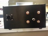
Here are a couple of pix of the messy insides and the rear panel - a bit fuzzy sorry to say..
Here are a couple of pix of the messy insides and the rear panel - a bit fuzzy sorry to say..
Attachments
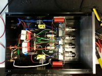
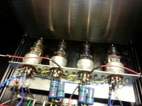
Congratulations! I must say I am surprised by this; does it compete with the original Muscovite? Internals look very rational to me. Nice looking vintage 6n14p-which seller has those? Valtek? Pity about the poor 6j9p- it does make a lovely triode though (as does the pentode section of 6f12p). I guessed you have just confirmed that pentodes are more trouble than they are worth.
Hi Kevin,
I actually bought some 6j9p (also some 6j49p) after reading an article in Jan Didden's linear Audio Volume 0.
It has an article written by a gentleman named Frank Blöhbaum which shows what he call the BestPentode circuit. I was impressed by the data he got compared to the D3a from this cheap tube.
I googled and found this link: forum.zelfbouwaudio.nl • Toon onderwerp - BestPentode, een nieuwe schakeling
Have you seen that circuit before? It might address some of the issues you have had with the screen caps.
Mogens
- Status
- This old topic is closed. If you want to reopen this topic, contact a moderator using the "Report Post" button.
- Home
- Source & Line
- Analogue Source
- The Muscovite Mini II 6N14P Phono Stage