I implemented a variant of the first circuit shown a couple of posts back, the only difference of note is that I used a 0.22uF capacitor rather than the 0.1uF capacitor I specified, this pushes the -3dB point down to 0.7Hz which means that there should be no phase shift of note within the audio passband due to the addition of this change.
Predictably I am going to tell you that the quality of this capacitor is as important as any to the overall performance of the phono stage, the saving grace is that you can use a 100V part here if you can find one.
Note that I changed the value for C1 to 0.33uF as this will further flatten the LF response, however the original 0.22uF will provide adequate performance as noted earlier in the thread. (Large film caps are expensive)
Attachments
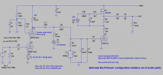
See information on the cascode front end. Note that there are a number of good operating points, I chose this one to take advantage of the IR LEDs on hand. Good operating points can be selected with effective input tube biasing in the range of -1 to -2V, as bias voltage goes up plate current and transconductance both drop for a given plate voltage as you'd expect.
Hey Kevin, I was breadboarding the 6J9P version but since a dozen 6n14p tubes arrived today I'm thinking about just shifting to that (this!) version. But I'd hoped for more like 48-50 dB or so from this amp. You mention in the image attached to this post (post 11) that increasing B+ and the load resistor will increase dB (from the increased voltage swing I assume). How do I calculate the dB increase from any change in B+ and the load resistor so that I can adjust to that overall gain?
Edit: just did some more thinking about this and I'm backtracking and thinking 45-46dB would probably be fine. Still, as an exercise, I'd be interested in learning about how this works.
Thx!
Last edited:
I'm doing some thinking about enclosures so I have one more question. Would tube shields be adequate shielding for this amp or should it really be enclosed in a metal box. Note the PS will be enclosed in a separate box, but there will be exposed AC wiring and tube amp trannies not too far away. Tube shields work reasonably well on a 12AX7 phono stage I have.
The pre-amp should be built in a metal box with a bottom cover. You can use tube shields, but I prefer placing the entire pre-amp inside a metal box.
Given how you are powering the unit you are not going to have the voltage headroom required to increase the gain to the levels you suggest you need with the 6N14P which require a doubling of the plate load resistors in the first stage.
Using the output stage follower version that I came up with will net you several additional dB of gain and significantly close the gap. You already have those details. (See post 81)
For the SSHV2 you will want a raw DC of 320V minimum at low line, a little additional margin is a good idea, but ultimately you don't want too much in order to keep the dissipation in the regulator reasonable. A transformer with a 250V secondary should fit the bill nicely. I would recommend an EI over toroid here in order to minimize noise feed through from the mains. Mains filter and electro-static shield (antek has these) with a toroid are other options.
Note Antek inventory on many transformers seems limited now, and they have not responded to any of my recent email queries about availability. So I am not recommending them for the time being.
Wow, thanks for the thorough responses, Kevin. I would certainly go for the electro-static shield version if I went with Antek toroid, but I did notice large numbers of transformers out of stock. I recently ordered one for another project and it appeared in short order, so I suspect it's mostly a supply issue.
I think you're right re: the voltage, but I haven't decided what rectifier(s) to use and have to look at that and my choke to figure out how much drop I'll get. What's the current draw per channel? I tried working it out but haven't come up with a number yet.
I did notice the extra bump in gain from the latest mu follower version, and given I may not need quite as high gain as I at first thought, it should be fine as is.
No reason to use a choke or CLC with the SSHV2, it has extremely high ripple and noise rejection. A capacitor of 220uF/450V should be quite sufficient.
The current demand will vary a bit depending on the tubes used, if you set the CCS in the SSHV2 for 50mA this should be adequate.
The current demand will vary a bit depending on the tubes used, if you set the CCS in the SSHV2 for 50mA this should be adequate.
I've built the LT1084-based heater circuit and tested it. I'm getting about 6.47v out of it. Three questions. First, what is the target voltage of the circuit? I'd expect 6.3v for the tubes but based on the data sheet it looks more like 5.3v (from R = R2/R1 x 1.25 - note R2 is actually R1 in your circuit and R1 is your R2). Are you running the tubes a little starved or is something else going on with the diode present? I measure the resistance between the output and adjust pins at the moment at just about 100R, which makes puts formula at 6.375v.
Second, I know too much voltage can reduce tube life, so is my voltage likely to be a problem? The 6S3P says max heater voltage of 6.6v and the 6N14P says 6.9v, so I'd think it would be fine, but my experience is pretty limited. Note line voltages don't appear to vary very much at my house.
Second, it seems like as R1 in Kevin's schematic (R2 in the generic LT1084 schematic) decreases, the output voltage should also decrease (it's the numerator). Kevin calls for a 510R resistor in that position. I measured mine at 503R or so, so I expected my output to be lower than the target. As it happens, this lower value is still putting my voltage considerably higher than the math would suggest. Any thoughts on why that would happen.
Thanks!
Carl
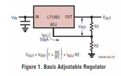
Target voltage is 6.3V. Correct equation is Vout = (R2/R1 + 1) x 1.25 which with the given component values results in a calculated output voltage of 6.39V. Using 1% tolerance resistors and assuming a ref voltage tolerance of 1% an RSS of these values gives +/- 1.7% tolerance on the output voltage or 6.28V - 6.49V, well within the acceptable range. The ignored Iadj will scew it in the direction of slightly higher voltage. (Did not calculate)
Note that I ignore Iadj at these current levels as it represents an error of <0.5%.. See below for full equation from the current LT data sheet.
Note that I ignore Iadj at these current levels as it represents an error of <0.5%.. See below for full equation from the current LT data sheet.
Attachments
Thanks, Kevin. I also ignored the Iadj, but somehow misread the rest of the datasheet. Anyway, thanks. Looks like I'm within the range.
I've finished up the breadboard, set my B+ using the SSHV2 to 299v and 50mA. I'll worry about precision later. Heater circuit is at 6.4v and all the heaters are glowing. When I measure at the plate of the 6n14Ps I'm getting about 275v or so on one tube, the other is close to B+, and that one bounces around and seems to climb back toward the 299v B+. I was expecting more like 180v or so on the plates of the 6n14P.
Seems like my tubes aren't conducting. I've swapped out the 6n14Ps and different tubes have different plate voltages, but not by much. The 6S3Ps don't seem to conduct at all. I have no signal input yet but thought this would conduct without a signal. Any ideas? (BTW, I did hook up an old TT briefly and all I got was severe buzz, seemingly related to grounding.)
Right now, all signal ground points go to the F0/S0 points on the SSHV2. A few ground points are combined near the tubes on a tag-board then brought to the F0/S0 points, so it isn't really a star ground. The only thing connected to mains ground is the shield for the heater transformer (it's on a piece of wood for now).
Finally, I started with the heaters NOT floating (voltage divider in the heater circuit not connected to signal ground). Now, when I connect that point to signal ground, my B+ at the output of the SSHV2 climbs to just under 300v, then falls dramatically over a minute or two to below 200v. I didn't check to see if/where it stabilized b/c the LT1084 was starting to get hot. Note the two 332R resistors (measured before installing) are currently reading about 166R each in circuit (in circuit shouldn't matter b/c there's nothing connected to the ground side of each so the reading should be just the resistors). I need to go over that entire circuit before doing anything else, but again if you have suggestions I'd love to hear them.
Check for miswired sockets, sounds like the connections are flipped. New job and not on the forum as much as usual.
Congrats, Kevin! I understand. I'm going check carefully and may end up pulling the entire build apart and re-wiring. It'll be easier the second time. I off-loaded the RIAA and the mu follower onto a perf board, so I don't have to re-build them...yet.
Question on "floating" the heater circuit. In the mini thread Kevin said to tie the voltage divider (from the two 332R resistors) to signal ground. When I tried this, tying to my signal ground which eventually ties to the SSHV2 "ground" connection, the B+ voltage dropped significantly over a minute or two. I switched off before seeing if it would stabilize. Any idea why this would happen? Have I misunderstood where to tie the heater circuit at the voltage divider? Thanks for any input.
You suspect you have mis-wired something or have a short in the socket due to a solder splash or similar. The two filament resistors connect to ground exactly as you describe, and their presence should have no effect on the B+ supply.
The only other possibility would be a filament to cathode short in the 6N14P..
The only other possibility would be a filament to cathode short in the 6N14P..
Thanks Kevin. I'm sure there's a mis-wiring somewhere since I've tried a number of 6n14Ps all with the same result. I've wondered about the pins that are supposedly tied internally. Not sure I tied them all together externally at the socket pins, so I'll check that. I blew a voltage transistor in the SSHV2 last night so have asked some questions there. Salas was wondering why the tie-in to signal ground with the heater supply. I can't really answer that.
I've made a minor revision to the design and started a new thread to discuss the changes here:
http://www.diyaudio.com/forums/anal...e-mini-iii-6n23p-phono-stage.html#post4314676
Preliminary listening tests seem to indicate that it is an improvement overall.
Gain is increased by 6dB by virtue of the higher transconductance of the 6N23P/6DJ8 which was one of my primary motivations.
http://www.diyaudio.com/forums/anal...e-mini-iii-6n23p-phono-stage.html#post4314676
Preliminary listening tests seem to indicate that it is an improvement overall.
Gain is increased by 6dB by virtue of the higher transconductance of the 6N23P/6DJ8 which was one of my primary motivations.
- Status
- Not open for further replies.
- Home
- Source & Line
- Analogue Source
- The Muscovite Mini II 6N14P Phono Stage