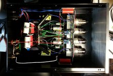
Congratulations! I must say I am surprised by this; does it compete with the original Muscovite? Internals look very rational to me. Nice looking vintage 6n14p-which seller has those? Valtek? Pity about the poor 6j9p- it does make a lovely triode though (as does the pentode section of 6f12p). I guessed you have just confirmed that pentodes are more trouble than they are worth.
I'd have to check on seller, but there are a number of good sellers on eBay - I went to one of my usual in Ukraine, getting more there given the unfolding situation might be risky.
I will probably investigate the pentode issue further, but as far as this design goes I am really happy with the performance of the 6N14P cascode with just minor tweaks. I will probably examine other operating points on the bench at some point as there are several that look equally promising relative to the one I choose.
So far based on current experience I prefer cascode front ends to both pentode based front ends, and high miller capacitance triode based front ends with the tubes I am familiar with.
In terms of build quality you are very kind, this was my rehab project to regain lost manual dexterity after chemo, and it was designed for another tube as you know and bolt down Soviet era PIO foil capacitors which while surprisingly not bad were not the last word in resolution either. a lot of hacks and compromises. I am not a pretty builder, but in general my stuff tends to work predictably and is reliable so I don't worry much over it.
The Muscovite still has areas of obvious sonic superiority, and is even quieter than the Mini II, but the differences are much smaller than they were. The Muscovite wins easily in the top and bottom octaves, is slightly more dynamic, and sees significantly deeper into the sound stage. In general though they are identifiably mine and clearly related.
Yes,
I've seen the article and have been purchasing Linear Audio volumes for some time now.
In discussions with a friend we concluded that the performance of the best pentode circuit was pretty consistent with what you would expect from a hybrid cascode. Disconnecting the plate seemed to make relatively little difference in the measured gain according to the friend who tried this. (I haven't done this experiment as I am not a fan of mixing sand in the signal path with tubes.)
I have compared the D3A and 6J9P in pentode mode and found their performances to be quite similar, the D3A is a few dB quieter and a dB or two more linear, but the differences were remarkably small. Transconductance of the 6J9P over the range of 10 - 15mA was within 10% or better of D3A which surprised me a little. No question this is a very good tube, and my samples are beautifully made as well.
Hi Kevin,
I actually bought some 6j9p (also some 6j49p) after reading an article in Jan Didden's linear Audio Volume 0.
It has an article written by a gentleman named Frank Blöhbaum which shows what he call the BestPentode circuit. I was impressed by the data he got compared to the D3a from this cheap tube.
I googled and found this link: forum.zelfbouwaudio.nl • Toon onderwerp - BestPentode, een nieuwe schakeling
Have you seen that circuit before? It might address some of the issues you have had with the screen caps.
Mogens
Funny that I opened a new thread to talk about the new design, and we seem mostly to be talking about the old one.. lol And that's ok..
I've been working on further improvements to my PC sound card based audio measurement system and am making some progress with conducted noise, ground loops, and radiated RF which was present even with the PC shut off. The system is based on a Win XP box (mostly not connected to the internet) with an M-Audio 24192 sound card connected via Western Electric REP-111C repeater coils (telco talk for broadcast quality 1:1 isolation transformers) and tonight I decided that the whole thing should be powered off of a medical grade isolation transformer. (Everything remains safety grounded) The Pete Millet Sound Card Interface is modified to in order to fix so low frequency CMRR issues, is electro-statically shielded and fitted with selected line driver and receivers.
All of this is so that I can more accurately (and less embarrassingly) measure my designs and share the results.
See below.. The source is my Amber 3501A, grounding is external through the Amber, the signal level is 5.56mV at just under 1kHz. (I should have adjusted it, but not critical for these purposes.) Units are dBV.. There appears to be a 6dB amplitude offset error between the FFT and the amplitude measurement which I need to investigate - probably a configuration error I made in the software.
Attachments

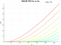
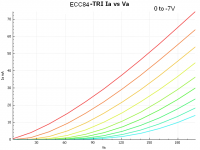
Some preliminary curves and tube models for the 6N14P and ECC84. The models and curves were generated in uTgui and represent the performance of a single section each of an unselected bogey device. I will post additional models when I have sense of what a representative device looks like parametrically.
These were unselected devices and I already know there is fair amount of variability of transconductance from sample to sample. (This is true of any unselected tube)
Note that I am running them with a bias of -1.2V effectively which seems to be a good place to operate them based on the curves. I believe that 2V may also be a good operating point, but anything much above this seems to be heading towards variable mu operation. Unfortunately I suspect this might not make such a good line stage tube...
It also appears that the ECC84 in cascode might realize a couple more dB of gain which is what the Philips data book based model I grabbed from somewhere on the net also predicts.
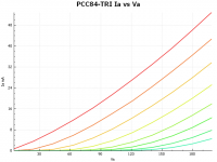
Interestingly the PCC84 performance aligns pretty closely with the particular pair of 6N14P currently installed in my phono stage. This might be the closest device of the lot I have measured so far. (Note I reduced the number of traces to 8, and the range is 0 to -7Vg)
.SUBCKT ECC84 1 2 3 ; P G C (Triode)
* Philips data book 1955
* library format: LTSpice 31-May-2008
X1 1 2 3 TRIODE MU=27.76 EX=1.309 KG1=492.0 KP=95.80 KVB=379.2 VCT=0.50 RGI=2000 CCG=2.8p CPG1=1.9p CCP=1.0p ;
.ENDS ECC84
* n* library format: LTSpice
* Traced by Kevin Kennedy 2014-04-18 in uTgui
* Unselected sample
.SUBCKT 6N14P-KK 1 2 3 ; P G C (Triode)
X1 1 2 3 TRIODE MU=26.21 EX=1.73 KG1=1196.1 KP=121.51 KVB=244.8 VCT=0.00 RGI=2000 CCG=2.8p CPG1=1.9p CCP=1.0p ;
.ENDS 6N14P
* n* library format: LTSpice
* Traced by Kevin Kennedy 2014-04-18 in uTgui
* Unselected sample
.SUBCKT ECC84-KK 1 2 3 ; P G C (Triode)
X1 1 2 3 TRIODE MU=20.08 EX=1.42 KG1=705.7 KP=569.16 KVB=456.3 VCT=0.00 RGI=2000 CCG=2.8p CPG1=1.9p CCP=1.0p ;
.ENDS ECC84-KK
* n* library format: LTSpice
* Traced by Kevin Kennedy 2014-04-18 in uTgui
* Unselected sample
.SUBCKT PCC84-KK 1 2 3 ; P G C (Triode)
X1 1 2 3 TRIODE MU=25.24 EX=1.38 KG1=658.8 KP=1065.54 KVB=474.6 VCT=0.00 RGI=2000 CCG=2.8p CPG1=1.9p CCP=1.0p ;
.ENDS PCC84-TRI
These were unselected devices and I already know there is fair amount of variability of transconductance from sample to sample. (This is true of any unselected tube)
Note that I am running them with a bias of -1.2V effectively which seems to be a good place to operate them based on the curves. I believe that 2V may also be a good operating point, but anything much above this seems to be heading towards variable mu operation. Unfortunately I suspect this might not make such a good line stage tube...
It also appears that the ECC84 in cascode might realize a couple more dB of gain which is what the Philips data book based model I grabbed from somewhere on the net also predicts.
Interestingly the PCC84 performance aligns pretty closely with the particular pair of 6N14P currently installed in my phono stage. This might be the closest device of the lot I have measured so far. (Note I reduced the number of traces to 8, and the range is 0 to -7Vg)
.SUBCKT ECC84 1 2 3 ; P G C (Triode)
* Philips data book 1955
* library format: LTSpice 31-May-2008
X1 1 2 3 TRIODE MU=27.76 EX=1.309 KG1=492.0 KP=95.80 KVB=379.2 VCT=0.50 RGI=2000 CCG=2.8p CPG1=1.9p CCP=1.0p ;
.ENDS ECC84
* n* library format: LTSpice
* Traced by Kevin Kennedy 2014-04-18 in uTgui
* Unselected sample
.SUBCKT 6N14P-KK 1 2 3 ; P G C (Triode)
X1 1 2 3 TRIODE MU=26.21 EX=1.73 KG1=1196.1 KP=121.51 KVB=244.8 VCT=0.00 RGI=2000 CCG=2.8p CPG1=1.9p CCP=1.0p ;
.ENDS 6N14P
* n* library format: LTSpice
* Traced by Kevin Kennedy 2014-04-18 in uTgui
* Unselected sample
.SUBCKT ECC84-KK 1 2 3 ; P G C (Triode)
X1 1 2 3 TRIODE MU=20.08 EX=1.42 KG1=705.7 KP=569.16 KVB=456.3 VCT=0.00 RGI=2000 CCG=2.8p CPG1=1.9p CCP=1.0p ;
.ENDS ECC84-KK
* n* library format: LTSpice
* Traced by Kevin Kennedy 2014-04-18 in uTgui
* Unselected sample
.SUBCKT PCC84-KK 1 2 3 ; P G C (Triode)
X1 1 2 3 TRIODE MU=25.24 EX=1.38 KG1=658.8 KP=1065.54 KVB=474.6 VCT=0.00 RGI=2000 CCG=2.8p CPG1=1.9p CCP=1.0p ;
.ENDS PCC84-TRI
Attachments
Kevin, maybe it's my eyes or the scaling, but your measured traces seem to highlight the variable mu character more than the Soviet datasheets do. An interesting question perhaps: what parameters make for good performance in a cascode circuit and are they any different from what is required for good linearity in a grounded cathode stage? If the upper cathode were fixed it would have to be constant gm for a fixed anode voltage but the upper cathode is not tightly constrained. Your actual distortion measurements show that 6n14p makes an excellent cascode. I wonder how ecc89 and other undesirables might perform.
Hi Nicholas,
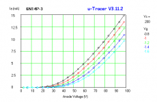
I have some better curves not taken with uTgui which is what I use to generate models, the Vg range is pretty wide, and given some software and hardware quirks in conjunction with the fairly steep transconductance characteristic of these tubes, small errors in grid voltage will scew the graphs making things look worse than they are. (This does not affect the models since all the variables measured are directly used to generate the model. There are other issues with the models lol) Note that at higher bias voltage values they do really appear to be variable mu, but given the signal levels present at the input, and the operating point chosen, they will never operate outside of their linear range. (This is sort of why I chose to use a 1.2V IR led for biasing)
I am running them over a very narrow range where there is no variable mu tendency at all (-2V and below), linearity measured quite well and the composite curves look pretty good in the data sheet.. I could actually do a composite measurement at some point.
Attachments
This morning while imbibing a nice hot cup of tea I installed a set of Mills MR-200 12.1K non-inductive wirewound resistors in place of the series string of 4.02K Roederstein MK-8 load resistors on the cascode, I expected at worst to be ripping them out shortly after listening to them, and at best concluding I wasted my money. In a perverse twist of fate neither of the above conclusions turned out to be true.
I'm am not sure why exactly, but they were a pretty audible improvement over the MK-8, the highs are considerably cleaner sounding. Given the comparable cost (fairly cheap actually for the level of precision) I guess I will just go with them..
Since this design uses absolutely no feedback it comes to me as no surprise that passive components are audible to some extent in some locations in this design. Things like voltage coefficient, excess noise, and nonlinear termination behavior are all relevant and measurable at least under some circumstances.
Next up is to evaluate the ECC84 MKC sent me recently. I suspect the gain will increase a couple of dB, otherwise performance should be similar. (good for this application)
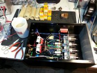
Anyway here are some more pix..
I should mention that eating and soldering is a NO NO.. Drinking tea is frankly questionable, but I'm not putting my lead covered fingers in the cup or my mouth so..
I just switched to Cardas silver solder, happy to report the flux is much less smoky that either Kester or Wonder.
I'm am not sure why exactly, but they were a pretty audible improvement over the MK-8, the highs are considerably cleaner sounding. Given the comparable cost (fairly cheap actually for the level of precision) I guess I will just go with them..
Since this design uses absolutely no feedback it comes to me as no surprise that passive components are audible to some extent in some locations in this design. Things like voltage coefficient, excess noise, and nonlinear termination behavior are all relevant and measurable at least under some circumstances.
Next up is to evaluate the ECC84 MKC sent me recently. I suspect the gain will increase a couple of dB, otherwise performance should be similar. (good for this application)
Anyway here are some more pix..
I should mention that eating and soldering is a NO NO.. Drinking tea is frankly questionable, but I'm not putting my lead covered fingers in the cup or my mouth so..
I just switched to Cardas silver solder, happy to report the flux is much less smoky that either Kester or Wonder.
Attachments
I just switched to Cardas silver solder, happy to report the flux is much less smoky that either Kester or Wonder.
If you like smoke and fumes, try Cardas rosin flux paste.😀
jeff
Hey Jeff,
I have a vague recollection of having used some a while ago, very acrid smoke. Rosin in general is pretty obnoxious whether in paste or liquid form, both before and during soldering, and boy is it sticky if you get it on hands or clothes. Fluxed solder must have been quite an innovation when it arrived on the scene long ago. 😀
I have a vague recollection of having used some a while ago, very acrid smoke. Rosin in general is pretty obnoxious whether in paste or liquid form, both before and during soldering, and boy is it sticky if you get it on hands or clothes. Fluxed solder must have been quite an innovation when it arrived on the scene long ago. 😀
... I installed a set of Mills MR-200 12.1K non-inductive wirewound resistors in place of the series string of 4.02K Roederstein MK-8 ...
kevinkr,
Knowing your love for (still) cheap Soviet surplus 😀, have you ever tried their wirewound C5-1 or C5-5 resistors somewhere in the signal path? They were made in relatively high values back in the day, up to 100k or so.
Last edited:
You can get Mills MR-200 from Michael Percy (Maine) in values all the way to 1M.. He keeps a good stock. I imagine shipping to the UK would be quick, but probably much more costly than the reverse. (Wouldn't hurt to ask I suppose. We generally don't get hit with customs fees for articles in the mail.)
Michael Percy Audio Ordering Information
Michael Percy Audio Ordering Information
Sadly, in the UK, for some unknown reason, we get hit with very high custom charges for items from the US. For the cases where I need high value wirewounds I content myself with the vitreous enamel Welwyn W23 series.
Hi,
In Belgium you add 9% ex-EU import tax plus 21% VAT, add shipping costs and you soon find out it's rarely worthwhile.
Wirewounds often sound better (cleaner) than metalfilm resistors.
Having a high-gain stage is the ideal playground for getting an idea about how "passive" components sound.
Ciao, 😉
Sadly, in the UK, for some unknown reason, we get hit with very high custom charges for items from the US.
In Belgium you add 9% ex-EU import tax plus 21% VAT, add shipping costs and you soon find out it's rarely worthwhile.
I'm am not sure why exactly, but they were a pretty audible improvement over the MK-8, the highs are considerably cleaner sounding. Given the comparable cost (fairly cheap actually for the level of precision) I guess I will just go with them..
Wirewounds often sound better (cleaner) than metalfilm resistors.
Having a high-gain stage is the ideal playground for getting an idea about how "passive" components sound.
Ciao, 😉
I have generally used Holco (the old good ones) and only used the Roederstein as a port of last resort. The Mills are definitely better.
I made some changes to the TT late yesterday - kludged my clone 3012 onto a plinth not intended to take it. I'm not sure all is well and will be taking things apart shortly to have a look.
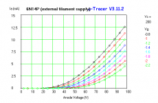
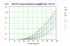
Since we have been talking about some apparent variable mu behavior observed in the uTgui curves (could be other issues since this is beta software) I have some additional curves taken using the uTracer software and on several different 6N14P over a range of grid bias voltages which I think are within the useful range. These all look quite well behaved.
I made some changes to the TT late yesterday - kludged my clone 3012 onto a plinth not intended to take it. I'm not sure all is well and will be taking things apart shortly to have a look.
Since we have been talking about some apparent variable mu behavior observed in the uTgui curves (could be other issues since this is beta software) I have some additional curves taken using the uTracer software and on several different 6N14P over a range of grid bias voltages which I think are within the useful range. These all look quite well behaved.
Attachments
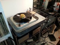
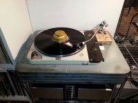
Fixed the arm mounting issue and was able to tweak things to the point where the protractor is almost happy. A whole lot better than before..
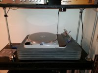
The first two are the table that the Muscovite Mini II is connected to (you can see it), and the third is the reference table which is connected to the Muscovite. SPUs on both tables, the Royal N is on an AT Technihard head shell.
The first two are the table that the Muscovite Mini II is connected to (you can see it), and the third is the reference table which is connected to the Muscovite. SPUs on both tables, the Royal N is on an AT Technihard head shell.
Attachments
- Status
- Not open for further replies.
- Home
- Source & Line
- Analogue Source
- The Muscovite Mini II 6N14P Phono Stage