


Tag got cut off the last one.
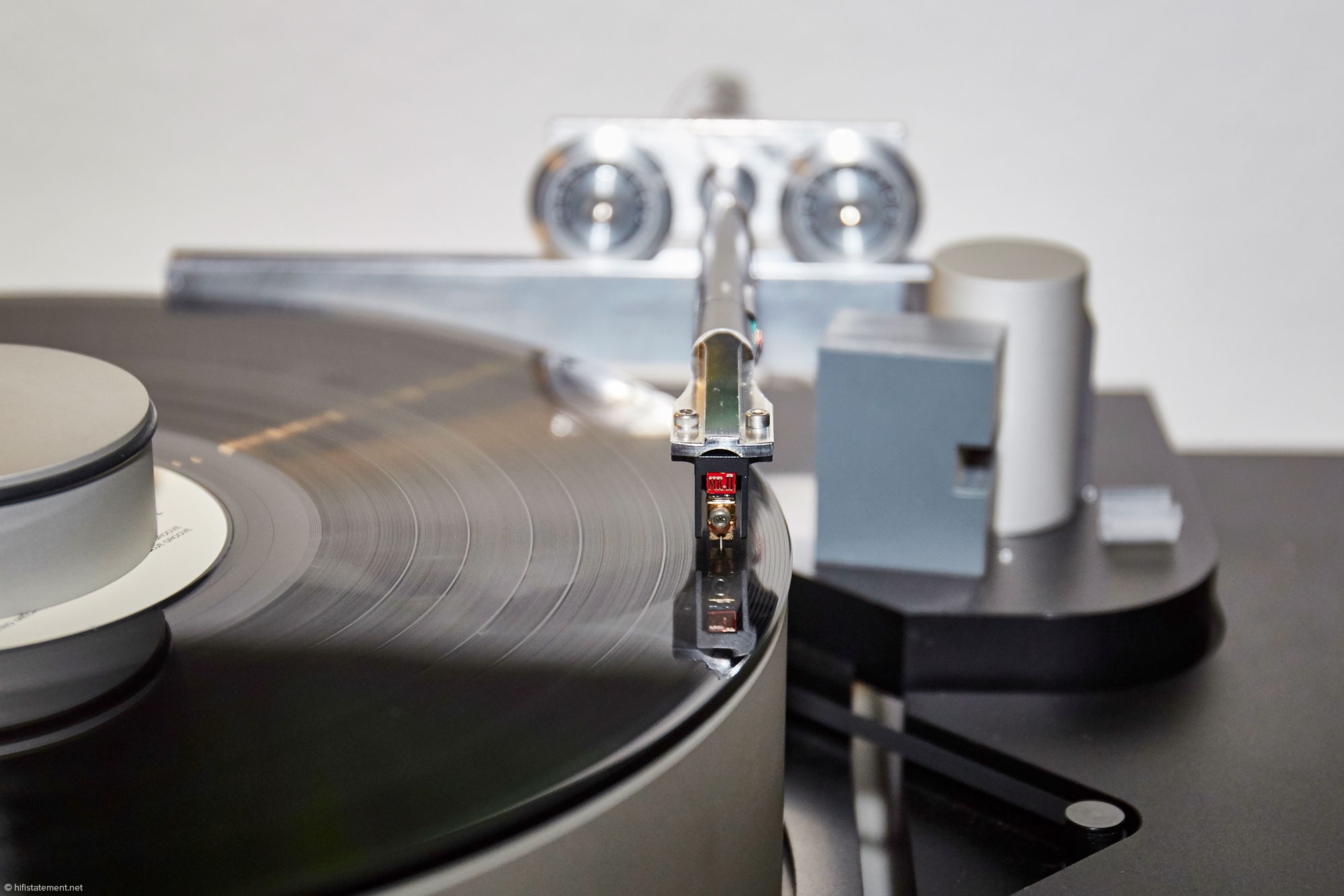
Carbon fiber tonearm made from golf club shaft. SME 3009 main bearing, effective mass 17grams
View attachment 721013
View attachment 721014
View attachment 721020
View attachment 721013
has anyone tried a radial magnetic bearing on a stainless shaft?
Neodymium Radial Ring Magnets - SuperMagnetMan - High Quality
im thinking the attraction forces may equal out each other with a steel shaft in the centre to allow it to suspend the magnet to act as the slider (or a pair of them to get a good base for a tonearm attachment)
if anyone has an idea of how to magnetize a rod to be opposite to the ring that would be even better.
i wonder if some form of dampening would be required - ie, running the magnet assembly through an oil trough or something
any thoughts on this?
has anyone tried a radial magnetic bearing on a stainless shaft?
Neodymium Radial Ring Magnets - SuperMagnetMan - High Quality
im thinking the attraction forces may equal out each other with a steel shaft in the centre to allow it to suspend the magnet to act as the slider (or a pair of them to get a good base for a tonearm attachment)
if anyone has an idea of how to magnetize a rod to be opposite to the ring that would be even better.
i wonder if some form of dampening would be required - ie, running the magnet assembly through an oil trough or something
any thoughts on this?
Unfortunately magnetic levitation using permanent magnets is impossible. Earnshaw's theorem proves this to be the case. At least one contact point is required to make the system stable. Partial levitation, where part of the weight of the carriage is supported by magnets is possible. I did investigate this approach but found that the magnets introduced a lot of damping to the movement and resulted in the system being massively overdamped. Further development could have possibly overcome this problem.
Niffy
It will not be stable. It is because magnetic force is inversely proportional with the square of distance. As soon as the rod is moved away from the centre, the closest part of the ring magnet will attract it more than the opposing parts, and eventually the rod will stick to the magnet.
radial rail TA
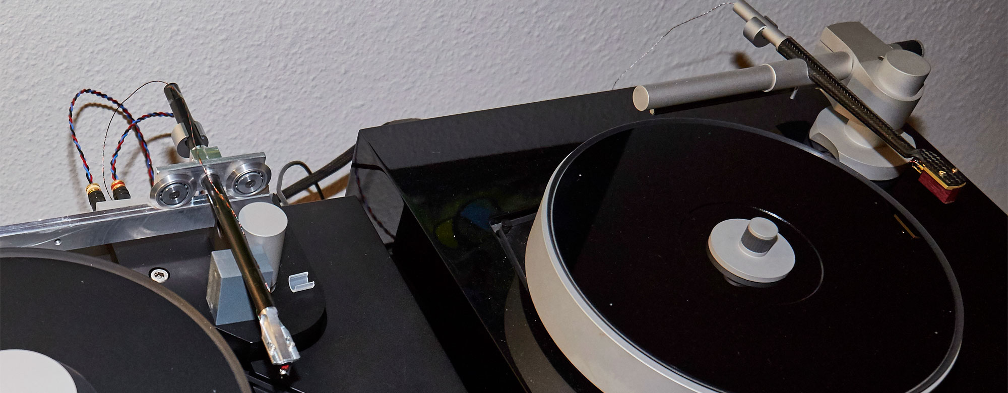
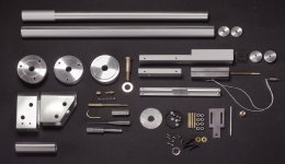
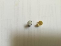
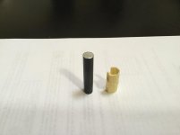
Parts done: quite difficult to get the proper precision without a mill (especially for parallelogram drilling), quite impossible the hoped lightness: some time wasted to get a 12 gr rail (at top in the photo): seemed beautiful, but after the slot cutting it sounded like an empty can of beer.
To be continued...
Merry Christmas to you all - carlo
Attachments
radial rail TA - first impressions
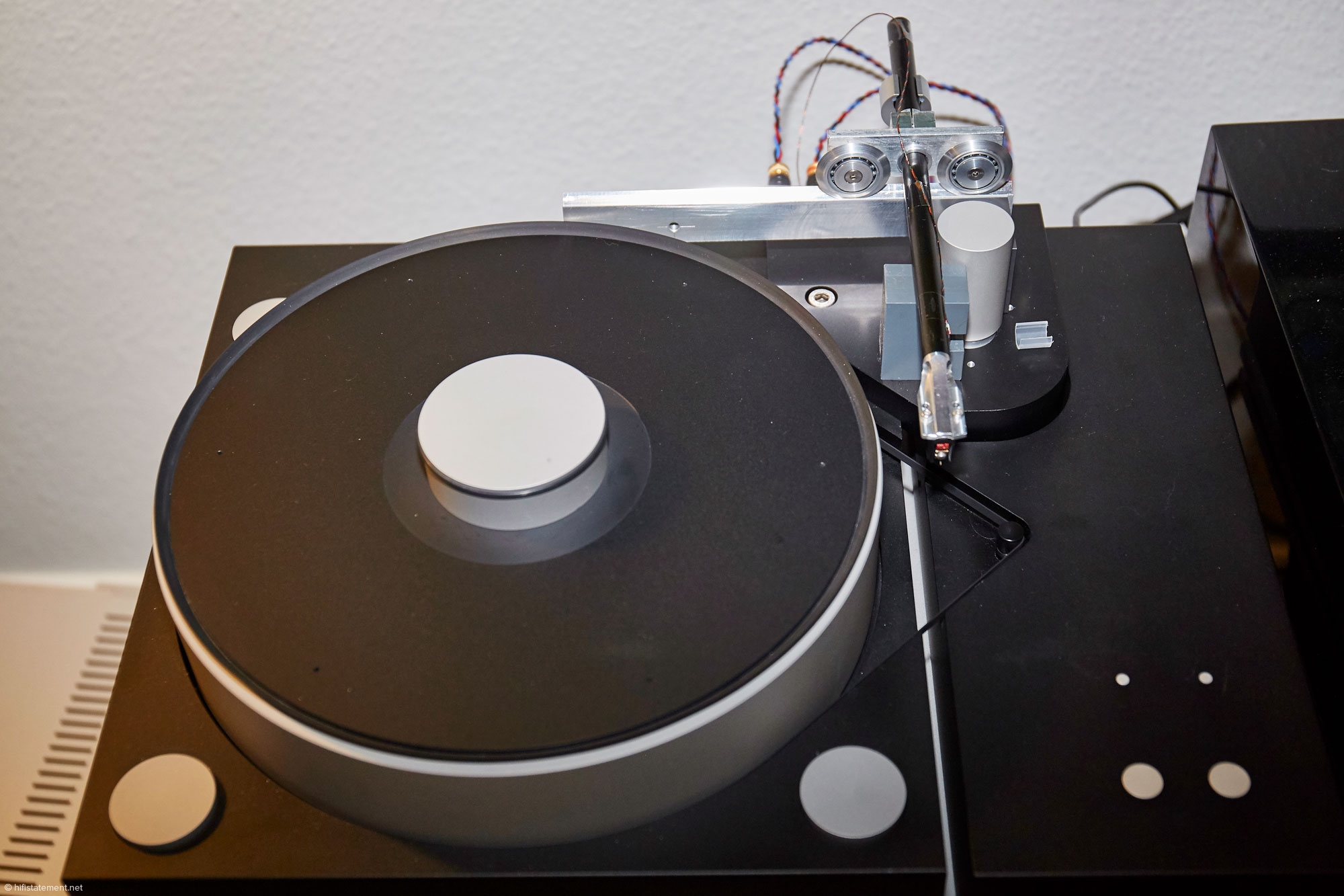
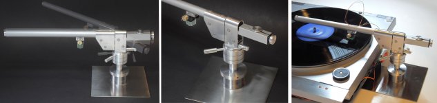
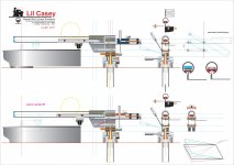
Lil Casey finally ended: a linear tonearm with radial rail and both articulations truly parallel (hor. vert.) . The first? who knows, it would be funny that no one ever tried....
How does it work
first of all it works, and with the linear ones it's not always guaranteed (you know what I mean). The reason for this design (to avoid the frictions due the torque on carriage) works; the side force is applied on axis without dispersions, so its behaviour is really different from what I know, including my # 2360 which used the same principle of non recirculating balls for sliding. Here on eccentricities is the carriage that moves back and forth, not the stylus.
Naturally the frictions must be the minimum possible, here we do not have the great advantageous momentum of a pivoted, only what's enough to track with high compliance cartridges and low VTF without servos, air pumps and so on. The carriage runs so well that the resistance of the cable (even thin as that in the photo) is much greater: I will try to make it softer and longer, with a wider loop.
The problem of carriage tilting exists, but it is enough an accurate setting of the small CW and some attention during the initial insertion: the variations of the stylus drag don't prevail over the self centering carriage.
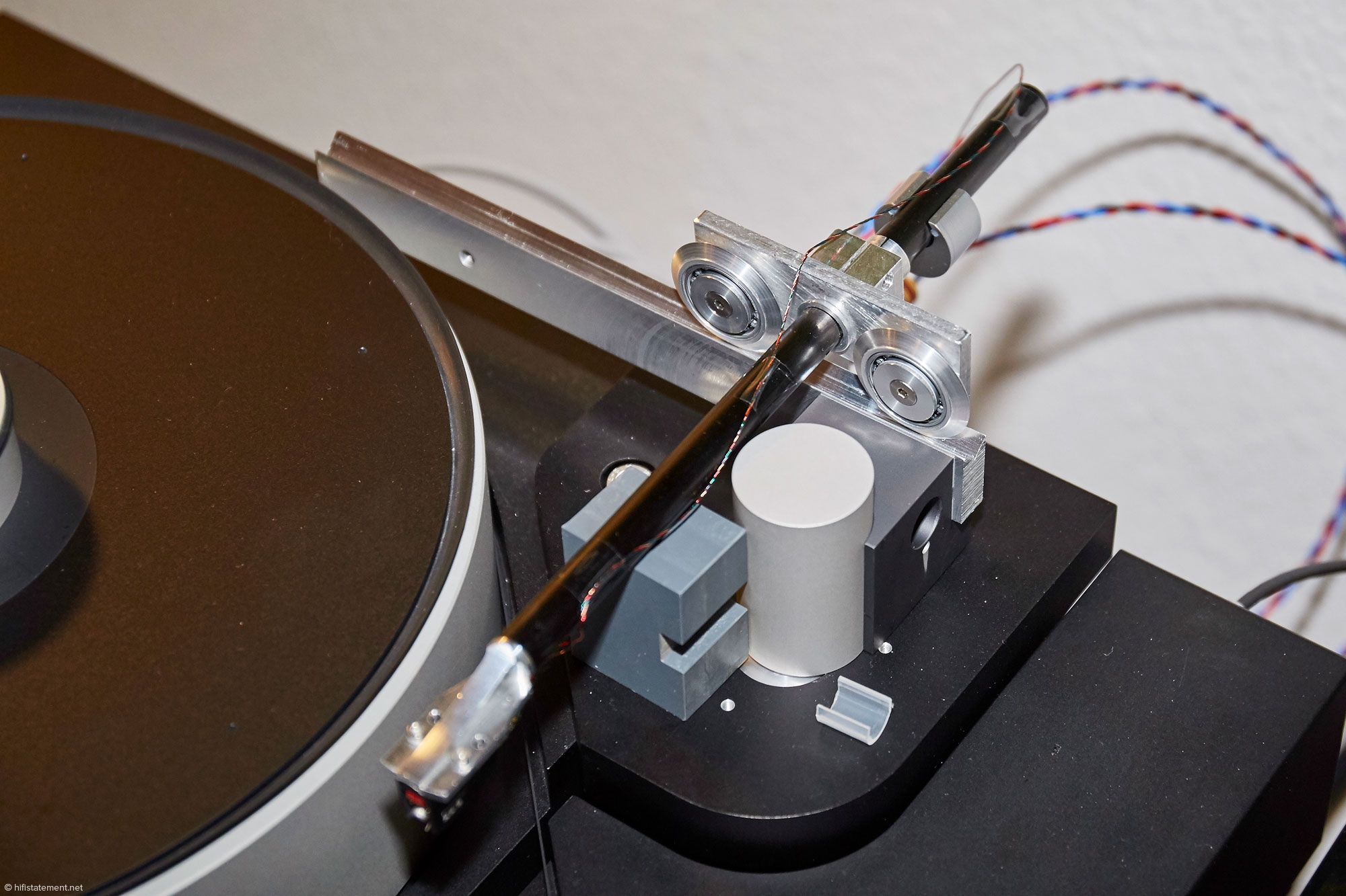
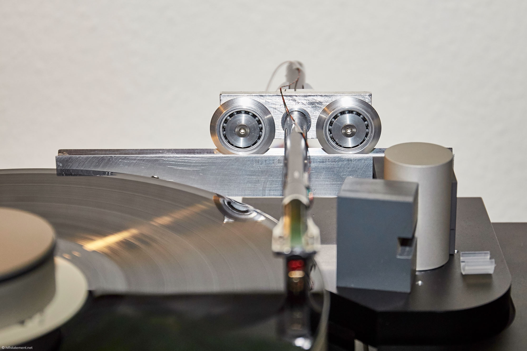
The vertical articulation of the parallelogram works too, but with 4 + 4 bearings we are really at the limit: on steep warps is the stylus at first to face the work (no good!). Lower weights (carbon fibers?) and better bearings (jewells?) are to try for sure ...
The trad CW is OK, and easy for fine adjustment. The spring CW behaves just as well, but the fine adjustment is really critical, perhaps the spring found is too short
Of course the base must be rotating for disc changing but, more, be adjustable for leveling: here just a slight inclination of the rail does not help at all, rather it damages a correct movement. The designed solution is compact and comfortable and the lifter rotates smoothly which is crucial for this kind of arm.
How it's made
I have already mentioned the difficulties of construction without a milling machine: more time lost in cutting and drilling templates than in parts themselves: a lathe for the base and other details is useful, but with patience, maybe assembling existing pieces you can also end the job.
What I had to give up is the lightening of the masses: a 12 gr rail, painstakingly built, was in practice completely useless. With aluminum what you get in lightness you'll pay in harmful resonances too. I've ended with a 37 gr total mass, cartridge included. I have used anodized ergal profiles, with very smooth and hard surface, good for rail and cart, but this limits available sections: a double vee non tilting carriage instead would make the arm more comfortable...
So:
another unbelievable Super Arm? no, just an experiment, a prototype: an open door, a road that deserves to be explored. Simple to conceive, not so to build: the problems foreseen by you all, and me, are partly still there, but can't impede the arm to play pleasantly. Now we can understand their real role, and imagine many possible improvements to work on.
Happy new 2019 - carlo
Lil Casey finally ended: a linear tonearm with radial rail and both articulations truly parallel (hor. vert.) . The first? who knows, it would be funny that no one ever tried....
How does it work
first of all it works, and with the linear ones it's not always guaranteed (you know what I mean). The reason for this design (to avoid the frictions due the torque on carriage) works; the side force is applied on axis without dispersions, so its behaviour is really different from what I know, including my # 2360 which used the same principle of non recirculating balls for sliding. Here on eccentricities is the carriage that moves back and forth, not the stylus.
Naturally the frictions must be the minimum possible, here we do not have the great advantageous momentum of a pivoted, only what's enough to track with high compliance cartridges and low VTF without servos, air pumps and so on. The carriage runs so well that the resistance of the cable (even thin as that in the photo) is much greater: I will try to make it softer and longer, with a wider loop.
The problem of carriage tilting exists, but it is enough an accurate setting of the small CW and some attention during the initial insertion: the variations of the stylus drag don't prevail over the self centering carriage.
The vertical articulation of the parallelogram works too, but with 4 + 4 bearings we are really at the limit: on steep warps is the stylus at first to face the work (no good!). Lower weights (carbon fibers?) and better bearings (jewells?) are to try for sure ...
The trad CW is OK, and easy for fine adjustment. The spring CW behaves just as well, but the fine adjustment is really critical, perhaps the spring found is too short
Of course the base must be rotating for disc changing but, more, be adjustable for leveling: here just a slight inclination of the rail does not help at all, rather it damages a correct movement. The designed solution is compact and comfortable and the lifter rotates smoothly which is crucial for this kind of arm.
How it's made
I have already mentioned the difficulties of construction without a milling machine: more time lost in cutting and drilling templates than in parts themselves: a lathe for the base and other details is useful, but with patience, maybe assembling existing pieces you can also end the job.
What I had to give up is the lightening of the masses: a 12 gr rail, painstakingly built, was in practice completely useless. With aluminum what you get in lightness you'll pay in harmful resonances too. I've ended with a 37 gr total mass, cartridge included. I have used anodized ergal profiles, with very smooth and hard surface, good for rail and cart, but this limits available sections: a double vee non tilting carriage instead would make the arm more comfortable...
So:
another unbelievable Super Arm? no, just an experiment, a prototype: an open door, a road that deserves to be explored. Simple to conceive, not so to build: the problems foreseen by you all, and me, are partly still there, but can't impede the arm to play pleasantly. Now we can understand their real role, and imagine many possible improvements to work on.
Happy new 2019 - carlo
Attachments
Hi all,
Defining my build:
passive , I want to use a Igus bearling liner “slide foil” as main bearing-without the housing. For both radial and lineair function
https://www.igus.com/product/964
Actually I want to use one for the W- type rails, but is not separately listed
Has a handy square protrusion to hook the arm on
Weight= 1 gram, 32 mm long, 12 mm shaft size
Hard anodized aluminium shaft (glass-not convinced yet)
Arm about 50 mm long, CF, shape don’t know yet
=========
Having red through the many, many pages of this thread, it struck me that the air pressure option has a wide following- my question: if you make a carriage capable of withstanding more than 3 bar (45 psi -about), as mentioned, you still need to move that mass with the needle/cantilever of the cartridge, even if the friction is low- is this too much- or just right?
Hissing a problem?
Also, I notice that there is some dark magic involved in setting up/designing the arm. Resonances, weights, distribution thereof, etc. Any rules of thumb, guidelines, do’s/don’ts? There is a lot in the thread, but is sometimes difficult to get a grip on
Thx, look forward to participate, your comments. apologies in advance for being a Noob
Coolerooney
Hello Coolerooney,
I hold Igus bearings in high regard and I am using them successfully in my own tone arm design.
However, I don't think that they will work correctly as carriage bearings in your application although I would be pleased for you if I am wrong! You can't beat air, jewel or ball bearings.
But go ahead and experiment. The Igus bearing is low cost.
Sincerely,
Ralf
Igus
Happy New Year all
Hi Ralf,’thx for the feedback
Where do you apply your Igusses?
Yes we’ll see, will check the friction numbers, I like the simplicity
If it freaks me out, I’ll go for full active, don’t like hooking up my turntable to life support;D
Rgds
Coolerooney
Happy New Year all
Hi Ralf,’thx for the feedback
Where do you apply your Igusses?
Yes we’ll see, will check the friction numbers, I like the simplicity
If it freaks me out, I’ll go for full active, don’t like hooking up my turntable to life support;D
Rgds
Coolerooney
Coolerooney A quick test: tie a thread from the bearing to your pivoted TA headshell. If it moves it's ok.
But consider that, due its offset, a pivoted exerts some more SF (the damn skating) than a linear one . And that on the carriage, friction increases frictions.
Walter: thanks for appreciation - of course you were joking. Low compliance: not jet, thinking that if a dog can pull the cart, it would be easier for a horse
carlo
Hmmm
While you were getting drunk last night....
I was paying my dues to the knowledge base
Ok, I now understand that a light arm is good, but that there must be a harmony between the cartridge compliance and the effective mass of the tonearm- and some other stuff
Ortofon has put it in a nice graph, so we don’t need to calculate and a Noob like me is happy
Resonance frequency
But wait, need the effective mass of my (future) arm
These guys take a decent stab at it:
http://www.kuzma.si/media/uploads/files/KAA 2016 LECTURE 2017.pdf
Check pages 17/18/19
But shies away from the whole enchilada
Mr Pierce has no qualms on this:
http://www.cartchunk.org/audiotopics/ToneArmMechanics.pdf
But he lost me after the 5th sentence
What I (we) need is a calculator in Excel to determine the effective mass of the arm, because without it a lot work done on optimising the arm is negated by a potentially suboptimal compliance matching.
Have requested mr Pierce if this is a possibility. But will most likely need additional data on materials used.
Coolerooney
Walter: thanks for appreciation - of course you were joking. Low compliance: not jet, thinking that if a dog can pull the cart, it would be easier for a horse
carlo[/QUOTE]
Yes and no at the same time. I think, if our civilization was moving on the right direction, such innovative ideas should be rewarded by society, regardless of: if a person has financial and promotional resources to make a commercially viable product of his idea, make it profitable, and protect his rights. Unfortunately, apart from China, it looks, like nobody cares about new technical ideas... With exception of military, of course.
Sorry for going off-topic.
As to low compliance, with a tonearm you will never know for sure, how it will sound, until you try and listen. Calculations are good, as a starting point only. IMO, of course.
Last edited:
- Home
- Source & Line
- Analogue Source
- DIY linear tonearm