@warrjon I did encounter a few design issues with the clamp approach. Mainly that by setting the rails into the GFS this by default brought the pivot axis down. With my design the smallest wheel diameter possible is 17mm with an axle diameter of 2mm. I’m planning on using 1.2mm TC for the pivot points and sapphire watch glass wheels. Your rail carrier/clamp would have to be reduced in height to accommodate the axle shown in the render. This may impact on rail stiffness, IMO stiffness of the rail is a crucial part of this system. The wheels however, do look the business, beautiful!
S.
S.

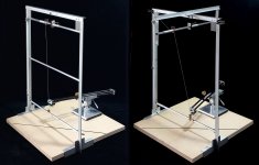
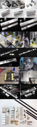
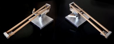
@Sether my rail design is slightly different to yours. I've gone with 6061 T6 aluminium CNC machined so the 4mm rods drop in a pocket, I have already used this rail assembly and know 16mm OD wheels will fit and operate correctly. With all the work so far to ensure everything runs as true as possible I was scratching my head with a way to hold the carbide rods straight while the epoxy sets.
Rails are on the right. There is a 3mm channel machined in one end of the rail so the carriage can be easily installed.

Rails are on the right. There is a 3mm channel machined in one end of the rail so the carriage can be easily installed.
They look very nicely machined!
I see, so the clamp would be temporary while gluing up. Is there not a possibility of ringing in an all aluminium carrier? I would have concerns that the cross section could act like a truncated tuning fork. I would be tempted to make the clamp a permanent component from a dissimilar material. Another option would be to adhere with a flexible adhesive (hybrid PU) with a very thin glue line a dissimilar material to the underside. This works with great results in speaker cabinet construction to reduce resonance. You could easily test this by supporting the rail assembly either end and gently tapping. Temporary adhere some material such as thin balsa, 1/32” birch veneer or any thing else lying around the bench with carpet tape, I’m sure you’ll hear a difference.
S.
This time all the machining has been done by a friend who is a Toolmaker on 4 and 5 axis CNC machining centers. He's done a great job. The rail was machined from much larger stock and constantly rotated to stress relieve the Al.
I'm not in the damping camp. I've done a lot of resonance testing of arms. Adding damping alters the resonant behavior and in some instances can make the situation worse by lowering the fundamental resonance. I believe in making the item as stiff as possible and minimal or no damping. This is why the aluminium carrier is as short and thick as possible. Gluing the TC rods in the Al provides enough additional stiffness and and damping to shorten the ringing decay time to more than acceptable level.
What I want is the Al rail to sink energy away from the carriage into the bridge and plinth. At every joint in the system there will be transmission and reflection of energy. My goal is to reduce the number of dissimilar materials with vastly differing acoustic impedances to allow energy an easy path out of the carriage with minimal reflection.
Unless your turntable is in another room, your sink might already have induced resonance from the loudspeakers. The clear audio gantry format which is what I’ve decided use, intrinsically is a large part. Much more susceptible to room induced resonance than a traditional pivot arm. I think your sink cannot be seen as a one way resonance drain, there’s a high chance of it propagating unwanted energy back into the rail.
S.
S.
My TT is in another room on a Minus K.
Even through my TT is in another room 10m from my system, airborne feedback is still audible in the TT/arm assembly with a stethoscope but not audible in the POM platter. Once playing an LP the airborne acoustic feedback is inaudible over the energy coming off the LP anywhere on the TT. There are no free lunches and the energy coming from the cartridge swamps any airborne acoustic feedback. Play an LP and a tone played through the speakers and the tone cannot be measured on the TT anywhere. It's a good 90dB below the program material measured with a HP spectrum analyser, basically in the noise floor.
I have spent 6 years developing my SP10 to reduce both airborne and seismic feedback. The SP10 now no longer resembles an SP10 due to the extensive modifications.
A truly awesome setup, something unobtainable by most. I don’t think my marriage would survive this level of dedication!!! I think my design goals are very different to yours, I just want to build the best turntable that I can out of junk lying around my workshop for as little cost as possible.
S.
S.
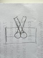
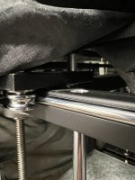
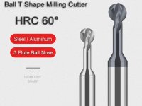
I had a thought about your solid aluminium rail. This could be a good solution, eliminating any chance of rail distortion and the need for a gluing up clamp. Ball nosed T cutter slots, rails pushed in from one end, locked if needed depending on tolerance with grub screws. This method is used on some 3d printers, see pictures.
S.
S.
Attachments
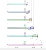
Easy Π, a true linear pivoted (ie linear on a radius, not tangential on the Thales circle), p.256 #5112
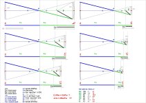
To each one (or two?) interested, sorry for the delay, I listened to music more enjoyable than test discs.
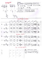
After the warp+eccentric tracing test, already posted, here are my usual tests with the reverse pendulum for the friction due to SF, SD and also the SF+SD at 45° (verifying a promising simulation in Algodoo) and a new one with my "Torquemada" gadget, to check the coherence between the two articulations (elliptic vs circle headshell motion).
Useless wasting time with subiective comments on tests, everyone may compare them easily with his linear realizations
Added also some photos of the build process, which requires (without a mill, or someome else) some more patience than usual, and a very accurate assembly jig.
Then some thoughts on this "strange" geometry and possible developments (some sketches and calculation hypotheses, as well as simulations and a verification mockup) in order to get smarter levers, better bearings, and less effective mass = a long way to.
Merry Christmas and a Happy New TA - carlo
To each one (or two?) interested, sorry for the delay, I listened to music more enjoyable than test discs.
After the warp+eccentric tracing test, already posted, here are my usual tests with the reverse pendulum for the friction due to SF, SD and also the SF+SD at 45° (verifying a promising simulation in Algodoo) and a new one with my "Torquemada" gadget, to check the coherence between the two articulations (elliptic vs circle headshell motion).
Useless wasting time with subiective comments on tests, everyone may compare them easily with his linear realizations
Added also some photos of the build process, which requires (without a mill, or someome else) some more patience than usual, and a very accurate assembly jig.
Then some thoughts on this "strange" geometry and possible developments (some sketches and calculation hypotheses, as well as simulations and a verification mockup) in order to get smarter levers, better bearings, and less effective mass = a long way to.
Merry Christmas and a Happy New TA - carlo
Attachments
-
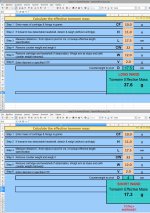 E M CALC.jpg451.1 KB · Views: 114
 -
 E Pi pendulum-.jpg281.1 KB · Views: 116
 -
 E-PI PENDULUM.jpg198 KB · Views: 132
 -
tort-a_ok.mp41.5 MB
-
 EASY PI DIYING s.jpg241 KB · Views: 133
 -
 E PI abc RATIO.jpg51 KB · Views: 118
 -
E Pi GEOM3.mp4554.3 KB
-
 calc.jpg267 KB · Views: 117
 -
E PI 12 INCH.mp4698.6 KB
-
 MODDED MOCKUP.jpg108.5 KB · Views: 125
Last edited:
Yes, and No, Niffy
Yes - the pendulum confirms my simulations, the arm does not move with mere SD even by increasing mg to 15 gr with 100 mm displacement - in all positions - Right - Center - Left.*
No - I don't know if there is 0 skating, because as soon as the traction is a bit off-axis, SD seems collaborating with SF - the 45° test was aimed at precisely this, since the sim was the most favorable. (see data on my pencil notes - quite coincident 90° vs 45° measurements)
My guess is that the composition of forces perhaps explains the tracking shown in those videos #5112, up with my best radials despite quite a double stiction (10+10 BBs around!**). And maybe there is also a never full stiction, because the bearings rotate at different angles.
My idea that this strange contraption is damn complicated to understand, for me.
Thanks R, N, S, M carlo
* simply because the headshell can't advance, geometrically ?
**but with various favorable levers


- Home
- Source & Line
- Analogue Source
- DIY linear tonearm