...Glass vee bearings with small radii will support up to 200 milligrams. Larger radius points will tolerate much higher loads....
True, Niffy: but reading the full sentence, i hoped that those 5mm glass rods could withstand the stress even during the carriage handling. And i'm still optimistic: a point load is really high but well distributed by the glass stiffness, if it will be tightly fit (or epoxied) inside the brass support.
But previously there is another problem, could it be feasible?
carlo
Dahlberg, Warren - fur such work after the Dremel i've used a Proxxon EB5 - far better finish due far better bearings . Quote Warren, with the pivot on the dremel spindle grinding speed will be too small, + possible vibrations and off center
Last edited:
bearings sequel
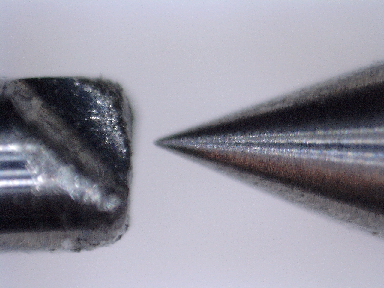
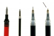
Making the Lil Casey mk2 with the parallelogram on pentips I have examined several. The Pilot G-Tec C4 seem to be made with a rough tech instead of the classic sophisticated machining: a micro tube with three spherical punchings as support for the sphere. But just look at the support sleeve*, turned with an incredible finish, to understand that the reason is simply to get much lower frictions, not to spare. The Pilot pens write much faster, and it's not just due their fluid ink.
Given the big stresses that can be generated on the parallelogram during the the arm handling, I couldn't use them due the weakness** of the micro tube, but for usual LT carriages some tests could be useful, since the cup becomes just a support, not a sliding surface
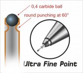
Fine line carbide sphere is 0.4 mm, the smallest around - a 12 refills box sells for 20 euro
carlo
* the micro tube (6,1 x 0,6 Ø mm) is easily detachable from the sleeve (pulling with small tweezers)
** relative: difficut to bend it while writing. or sketching
Making the Lil Casey mk2 with the parallelogram on pentips I have examined several. The Pilot G-Tec C4 seem to be made with a rough tech instead of the classic sophisticated machining: a micro tube with three spherical punchings as support for the sphere. But just look at the support sleeve*, turned with an incredible finish, to understand that the reason is simply to get much lower frictions, not to spare. The Pilot pens write much faster, and it's not just due their fluid ink.
Given the big stresses that can be generated on the parallelogram during the the arm handling, I couldn't use them due the weakness** of the micro tube, but for usual LT carriages some tests could be useful, since the cup becomes just a support, not a sliding surface
Fine line carbide sphere is 0.4 mm, the smallest around - a 12 refills box sells for 20 euro
carlo
* the micro tube (6,1 x 0,6 Ø mm) is easily detachable from the sleeve (pulling with small tweezers)
** relative: difficut to bend it while writing. or sketching
Attachments
Found on web this description in good english (sorry for mine)
The G-Tec-C4 also goes by the name Hi-Tec-C in certain other markets - same pen, same ink.
The production of a 0.4mm ball point tip has been achieved using the 3-dimples supporting system technology. In this system, the 0.4mm carbide alloy ball is mounted by making three depressions in the tip of a fine stainless steel pipe, in contrast to the traditional system of hollowing out the metal tip. Since the ball will be supported on 'points' the reduction in wear surface allows smoother rotation. The resulting stroke width is just 0.2mm.
I belive the drill/dremel "prof of concept" is good enough  So I have
ordered a couple of 2,5mm tungsten rods to make my own pivots. The drills I
have been grinding are only tungsten on one side and i rather fit just one
instead of two pivots to the "bearing wheel". I have decided to go for Niffys
"one ring/two rod" concept as well as I belive it has less possible fault percentage.
So I have ordered a couple of 2,5mm tungsten rods to make my own pivots. The drills I
have been grinding are only tungsten on one side and i rather fit just one
instead of two pivots to the "bearing wheel". I have decided to go for Niffys
"one ring/two rod" concept as well as I belive it has less possible fault percentage.
bearings sequel
Making the Lil Casey mk2 with the parallelogram on pentips I have examined several. The Pilot G-Tec C4 seem to be made with a rough tech instead of the classic sophisticated machining: a micro tube with three spherical punchings as support for the sphere. But just look at the support sleeve*, turned with an incredible finish, to understand that the reason is simply to get much lower frictions, not to spare. The Pilot pens write much faster, and it's not just due their fluid ink.
Given the big stresses that can be generated on the parallelogram during the the arm handling, I couldn't use them due the weakness** of the micro tube, but for usual LT carriages some tests could be useful, since the cup becomes just a support, not a sliding surface
Fine line carbide sphere is 0.4 mm, the smallest around - a 12 refills box sells for 20 euro
carlo
* the micro tube (6,1 x 0,6 Ø mm) is easily detachable from the sleeve (pulling with small tweezers)
** relative: difficut to bend it while writing. or sketching
Carlo,
Good research on ball point pens. I found this on Amazon. It is .3 mm.
Amazon.com: Pilot G-Tec-C Black Micro Fine 0.3mm - 12 Pack Gel Pen - PGTC3-BLK: Health & Personal Care
Jim
There is some confusion around: often the number refers to the line they can produce. 0,4 ball = 0,2 ; 0,7 = 0,4. difficult to find the ball diameter, but 0,4 seems the smaller.
Usual ball pen use mainly 0,7 balls - gel pens 0,5 but inside usual turned bushing.
I've used those Pilots for years at work, sometimes replacing more precise but delicate Rapidographs: if you don't press too much is difficult to bend them.
Who knows if they could be a poor man's jewel: they are available worldwide, and cheap too
carlo
There is some confusion around: often the number refers to the line they can produce. 0,4 ball = 0,2 ; 0,7 = 0,4. difficult to find the ball diameter, but 0,4 seems the smaller.
Usual ball pen use mainly 0,7 balls - gel pens 0,5 but inside usual turned bushing.
I've used those Pilots for years at work, sometimes replacing more precise but delicate Rapidographs: if you don't press too much is difficult to bend them.
Who knows if they could be a poor man's jewel: they are available worldwide, and cheap too
carlo
Personally, I still prefer precision pivots. It is not too expensive either. However, if precision pivots are not available, ballpoint tips may be an option.
Jim
Me too -
precision pivots can be still machined, with skill and tools, as Warren and Dahlberg are doing now. It's the Vee cup that's the difficult part: using carbide for pivot one has to find an harder material for the cup. There are very few: ruby, sapphire (just order some thousands pcs): to be on the diy side i've suggested to try the pyrex rods, or the hard anodization, but without knowing if it is really feasible.
Pen tips bring surely more friction, but the cup is no more a problem, the ball rotates on it's seat, not on the cup surface.
And maybe better a very good pen tip than a bad homemade "jewel".
carlo
Hi Dahlberg,
Spot on on the end shake.
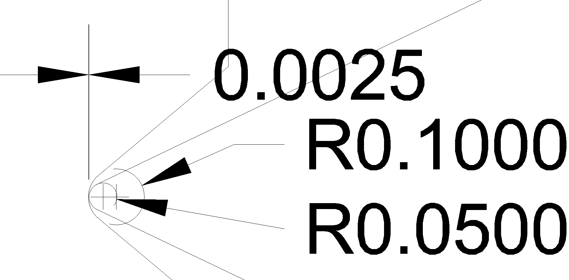
I still reckon that the dimensions you've chosen are too small. If you keep the cup radius the same and increase the pivot radius to 0.075mm you will more than halve the contact pressure. This does give a ratio of only 3:2 which is smaller than the recommended 2:1 to 3:1 range. Making the ratio in the recommended range will give optimum friction to load. In order to obtain the best friction to load relationship you would need to make both the pivot and the cup larger. If you are building your own bearing components then you can make them to an optimal size. I made my steel pivots with a tip radius of 0.125mm and the grub screw vees with a cup radius of 0.25mm giving a ratio of 2:1. An additional advantage of the larger size is that they are easier to make. I ran these for probably 6 months before I finally upgraded to the jeweled bearing system. They showed no signs of wear or damage and were used with a carriage weighing 55g Inc cartridge.
If you use the sizes as shown in your diagram you will actually need to reduce the maximum weight of the carriage to only 10g if you want to keep the contact pressure and shear stress to the same level as I had.
Niffy
Spot on on the end shake.
I still reckon that the dimensions you've chosen are too small. If you keep the cup radius the same and increase the pivot radius to 0.075mm you will more than halve the contact pressure. This does give a ratio of only 3:2 which is smaller than the recommended 2:1 to 3:1 range. Making the ratio in the recommended range will give optimum friction to load. In order to obtain the best friction to load relationship you would need to make both the pivot and the cup larger. If you are building your own bearing components then you can make them to an optimal size. I made my steel pivots with a tip radius of 0.125mm and the grub screw vees with a cup radius of 0.25mm giving a ratio of 2:1. An additional advantage of the larger size is that they are easier to make. I ran these for probably 6 months before I finally upgraded to the jeweled bearing system. They showed no signs of wear or damage and were used with a carriage weighing 55g Inc cartridge.
If you use the sizes as shown in your diagram you will actually need to reduce the maximum weight of the carriage to only 10g if you want to keep the contact pressure and shear stress to the same level as I had.
Niffy
Hi Dahlberg,
Spot on on the end shake.
I still reckon that the dimensions you've chosen are too small. If you keep the cup radius the same and increase the pivot radius to 0.075mm you will more than halve the contact pressure. This does give a ratio of only 3:2 which is smaller than the recommended 2:1 to 3:1 range. Making the ratio in the recommended range will give optimum friction to load. In order to obtain the best friction to load relationship you would need to make both the pivot and the cup larger. If you are building your own bearing components then you can make them to an optimal size. I made my steel pivots with a tip radius of 0.125mm and the grub screw vees with a cup radius of 0.25mm giving a ratio of 2:1. An additional advantage of the larger size is that they are easier to make. I ran these for probably 6 months before I finally upgraded to the jeweled bearing system. They showed no signs of wear or damage and were used with a carriage weighing 55g Inc cartridge.
If you use the sizes as shown in your diagram you will actually need to reduce the maximum weight of the carriage to only 10g if you want to keep the contact pressure and shear stress to the same level as I had.
Niffy
Thanks for the clearification
I'm not sure on how to take this further but making my own bearings all
together is tempting (it's diy audio we are doing right?
)Hardened stainless steel schould be pretty hard I guess.
Edit:
I recived a quote from "true point" for 4 vee's and 4 pivots @ 280$ incl shipping to Sweden
Well they need to make a living as well but.......
Last edited:
Even if you are planning on going the full jeweled route I would still recommend building your own first. This way you can iron out any problem before you try fitting the expensive bits. You don't want to glue your carbide pivots into an axle then discover that you would have been better off making the axle a centimetre longer. I discovered and found solutions to a couple of problems I had not anticipated.
Niffy
Niffy
There was supposed to be an "it" there as well
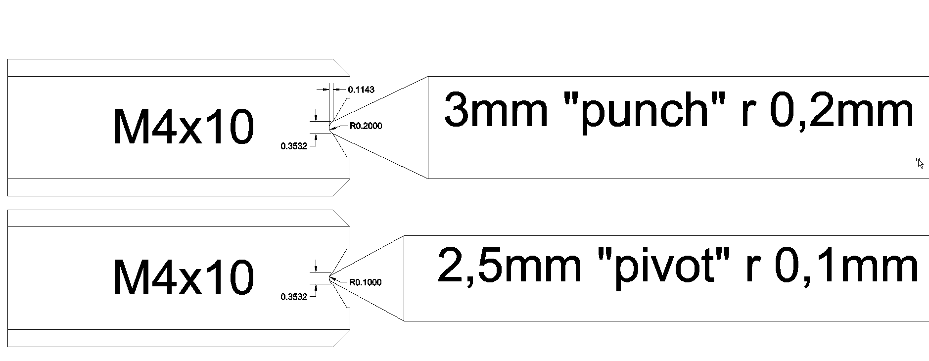
Using regular m4 stainless screws and at first grind them flat and drill a 2mm
hole in the centre. Manufacture a "punch" with the desired radius and I guess a
centering tool for the process to come. When this is done slam the punch with
an appropriated hammer to make a dent in the screw. The dent isnt that
deep or has a large diameter. The drawing says 0,35x0,1mm and that should be
possible since a 0,2mm radius is pretty sharp. For polishing I'm not sure but
some diamond paste in the hole and use the punch to grind it maybe
Just rotating the punch would help I think.
I'm thinking to make the "punch" from a 1mm tungsten drill.
Using regular m4 stainless screws and at first grind them flat and drill a 2mm
hole in the centre. Manufacture a "punch" with the desired radius and I guess a
centering tool for the process to come. When this is done slam the punch with
an appropriated hammer
to make a dent in the screw. The dent isnt that deep or has a large diameter. The drawing says 0,35x0,1mm and that should be
possible since a 0,2mm radius is pretty sharp. For polishing I'm not sure but
some diamond paste in the hole and use the punch to grind it maybe
Just rotating the punch would help I think.
I'm thinking to make the "punch" from a 1mm tungsten drill.
Last edited:
Hi Dahlberg,
I would not recommend making the punch out of a 1mm tungsten drill bit. If you hit it with enough force to indent the grub screw it will shatter. I used the shank from a 6mm cobalt drill bit. This will be much tougher, easier to work to the correct shape and much easier to hold whist you wack it with a hammer. Your drawing show quite an acute angle at the end of the punch. This angle should be 90°. Try and get the most accurate shape and best possible finish to the end of the punch. This shape will be imprinted into the end of the grub screw. Polishing is not intended to modify this shape, only its surface finish. The use of a soft applicator to apply the polishing paste is preferable (and much easier, I used a sharpened matchstick in a dremel).
The drilled pit in the end of the grub screw doesn't need to be as big as you have made it. I just broke the surface with a small centre drill bit making a pit just big enough to locate the punch. The vee is created by the punch not the drilling.
The use of a finer pitch thread for the grub screw will make adjusting the end shake much easier. I used 0.5mm pitch M3 grub screws. 0.35mm fine pitch M3 would be even better (if you can source them and find the correct tap for making the mountings).
I used stainless grub screws. Tensile steel grub screws (the black ones) could probably be used. The steel these are made from is harder so should work well. This grade of steel will rust so they will need to be used greased. I found that my steel vee bearings actually worked slightly better with a little bit of petroleum jelly applied.
Niffy
My plan is to use M3 12.9 set screws. Forge the VEE then quench harden them, don't worry about tempering as they have very little stress. Last step will be polishing.
Lanolin will stop rust in its tracks and is a great lubricant, if you don't mind smelling like a shearing shed. Also the more highly polished the steel the less it will tend to rust.
When I have made my forge I'll post some photos.
Niffy's right if you hit tungsten it will shatter. I dropped one of my carbide end mills on the vice and shattered the cutting edge. It's very hard but also brittle.
Last edited:
Here gathered some old watchmaking links, adding some new (to me) on pivot burnishing, and jewel grinding. (attachment)
Surely you know them, but maybe could be of some interest for others: sometimes it is useful to see what is talked about.
Now my eyes, and my hands are too old for this level of tolerances. Never bought a watch lathe or other tools without having the skill to use them properly.
carlo
my tip: 3mm fine pitch is difficult to find, but 2mm - 0,4 pitch screws and taps are common. Use a long screw in a long threaded hole and cut to measure after punching and so on: less play, better centering, less risk of deformations.
screws: no lubrication - after tuning put a drop of diluted acryl paint (will penetrate along the threads), as done by industry from a century. A drop of solvent to retune
How is made a 0,1 roundness? I can't imagine
Attachments
Last edited:
- Home
- Source & Line
- Analogue Source
- DIY linear tonearm