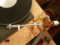
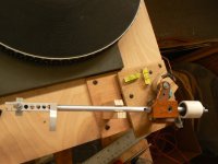
Hi Frank: Merry holidays to you, too (or hoppy holidays if you are having Christmas beer - grin). The arm base has been completed and bolted to the Marantz TT-1000, and we should soon be able to listen to the LT.
May I ask you one general question? In your experience (or opinion), how large does the horizontal tracking error need to be before it starts to be audible? I assume that the threshold may be different for the outer, central and inner LP grooves. Let's say that the LP is of soprano arias.
The technical fun of working out the puzzles is one thing, but how much impact this will have on the sound may be a somewhat different thing.
cheers, jonathan
Hello Frank, welcome back.
Frank has opened the bag and released a fairly critical cat (Schroeder's Cat?) with his suggestion about tracing a floating, non-circular pivot point. After wrestling with his LT design for a couple of years, I finally tried doing that trace. I tried hard to fit a circle to the trace, but it just wouldn't happen. I gave up and accepted the odd comma-like shape. Later, that same shape showed up in the plots 2wice posted back a bit and, interestingly I thought, in John Ellison's plot that DD just posted. I don't think Ellison understood what he'd found. If Jonathon connected the dots in his tables, he might find the same shape.
I think Ellison's plot also answers aligezhem's question about how the stylus can not trace a circle across the record: Because of the influence of the pivot, the forward motion of the swing arm is not linear.
I worked with the Birch Thales design partly because I could post the results without stepping on somebody's patent. There are side forces inherent in the Birch arm, but I've found they can be nulled fairly easily because of other inherent aspects.
I think I've come up with a way to use the comma shape guide, but unfortunately it will be mechanical rather than a magnet and will give up some important advantages. It is more difficult to build than the single fixed pivot and I haven't been able to do it yet.
Jonathon, if you solve the construction hurdles, my guess is that you'll be very pleased with the sonic results. I certainly hope so.
Frank - were you in Berlin for the lichtgrenze celebration? I thought it was absolutely beautiful.
Thanks again and best wishes.
Attachments
Hi Doug,
Yup, I was here for the celebration. The city appeared to be almost as packed as it did 25 years ago...")
Your last photo shows what I suggested very well. And it makes obvious that, by using this method, one can place the guide point anywhere it makes sense("real estate"- and force-wise). The required curve just won't be a circle segment
The guiderail then has to be made with a high degree of precision...
Btw, a circle can be seen as an ellipse with both focal points being congruent....
Determining the function for the ellipse one finds to work for your arm would help programming a CNC machine that mills the guide...
Cheers,
Frank
Yup, I was here for the celebration. The city appeared to be almost as packed as it did 25 years ago...
Your last photo shows what I suggested very well. And it makes obvious that, by using this method, one can place the guide point anywhere it makes sense("real estate"- and force-wise). The required curve just won't be a circle segment
The guiderail then has to be made with a high degree of precision...
Btw, a circle can be seen as an ellipse with both focal points being congruent....
Determining the function for the ellipse one finds to work for your arm would help programming a CNC machine that mills the guide...
Cheers,
Frank
The 2 pivot point can also be placed outside the curve, then you get a scissor motion that can be controlled with a belt drive. The main problem is the fact that skating forces varies much more with this kind of arm, to a degree where they are hard to handle Ina simple way, and where one can ask how sound degrading they may be
Last edited:
Hi Directdriver:
I wasn't necessarily suggesting an SME-style headshell, but some kind of detachable headshell would be convenient for cartridge installation (if accompanied by a precise gauge).
In the context of a Birch-style tonearm design, I can't think of any benefit in having the forward pivot capable of vertical articulation. If anything, placing the vertical pivot above the LP is a potential trouble-maker, since it guarantees that both effective length and VTF will change whenever a slight warp in the LP pushes the cartridge up and down.
IMHO it is better to integrate the vertical bearing with the guiding pivot P. The swing arm can then be of any length that you like - 6 inches would be fine, or even something as short as on Micha Huber's designs.
If you are referring to 43.32379mm, that comes from plugging your numbers of 320mm Thales circle diameter and 218mm swing arm length into the design methodology that I suggested in post #835http://www.diyaudio.com/forums/analogue-source/165878-angling-90-tangential-pivot-tonearms-84.html#post4146768, and letting step 7 calculate where guide pivot P should be and what the optimal diameter should be. A Birch-style tonearm should have three null radii (where the tracking error is zero), but if the guide arm length is inappropriately chosen, the number of null radii falls to 2 and the tracking error increases considerably. It is better to choose a swing arm length, decide where you want the three null radii to be, and let those tell you where to locate guide pivot P and the guide arm length.
It was for this reason that the 40mm length for the guide arm needed to be increased, and 43.32379mm was the number used for the table below (it is probably possible to round off some of the decimal points by choosing different null radii, but this would also change the tracking error peaks, and their distribution). Note that in this particular version of the table, the first number in each line is the pivot-to-spindle (D-A) distance. As before, the second number is the groove radius, and the third number is the tangency.
Thales circle diameter 320mm
swingarm length 218mm
guidearm length 43.32379mm
spindle-to-guide pivot distance 256.10914mm
spindle-guide pivot line vs. spindle-pivot line angle 2.856526 degrees
01. 263.15355mm 146.60098mm 90.20971 degrees +0.20971 (*)
02. 262.61582mm 145.78277mm 90.17168 degrees
03. 261.81506mm 144.5381mm 90.11989 degrees
04. 261.03157mm 143.29081mm 90.07449 degrees
05. 260.26365mm 142.0409mm 90.03474 degrees
06. 259.50984mm 140.78835mm 90.00000 degrees (#)
07. 258.76897mm 139.53317mm 89.96974 degrees
08. 258.03999mm 138.27535mm 89.94351 degrees
09. 257.32205mm 137.01493mm 89.92092 degrees
10. 256.61438mm 135.7519mm 89.90161 degrees
11. 255.91633mm 133.48628mm 89.88529 degrees
12. 255.22734mm 133.2181mm 89.87170 degrees
13. 254.54691mm 131.94737mm 89.86058 degrees
14. 253.87459mm 130.67413mm 89.85175 degrees
15. 253.21mm 129.39838mm 89.84499 degrees
16. 252.55281mm 128.12016mm 89.84014 degrees
17. 251.9027mm 126.83949mm 89.83704 degrees
18. 251.2594mm 124.5564mm 89.83555 degrees
19. 250.62267mm 124.2709mm 89.83553 degrees -0.16447 (*)
20. 249.9923mm 122.98304mm 89.83686 degrees
21. 249.36809mm 121.69282mm 89.83942 degrees
22. 248.74987mm 120.40028mm 89.84312 degrees
23. 248.13749mm 119.10544mm 89.84786 degrees
24. 247.5308mm 117.80833mm 89.85353 degrees
25. 246.92969mm 116.50898mm 89.86006 degrees
26. 246.33403mm 115.20741mm 89.86735 degrees
27. 245.74374mm 113.90346mm 89.97534 degrees
28. 245.15872mm 112.5977mm 89.88394 degrees
29. 244.5789mm 111.28963mm 89.89308 degrees
30. 244.0042mm 109.97943mm 89.90270 degrees
31. 243.43456mm 108.66715mm 89.91273 degrees
32. 242.86992mm 107.3528mm 89.92310 degrees
33. 242.31024mm 106.03641mm 89.93374 degrees
34. 241.75548mm 104.718mm 89.94460 degrees
35. 241.2056mm 103.3976mm 89.95561 degrees
36. 240.66056mm 102.07524 89.96672 degrees
37. 240.12034mm 100.75094mm 89.97786 degrees
38. 239.58492mm 99.42473mm 89.98897 degrees
39. 239.05428mm 98.09663mm 90.00000 degrees (#)
40. 238.5284mm 96.76666mm 90.01088 degrees
41. 238.00728mm 95.43486mm 90.02155 degrees
42. 237.4909mm 94.10124mm 90.03196 degrees
43. 236.97927mm 92.76583mm 90.04204 degrees
44. 236.47237mm 91.42865mm 90.05172 degrees
45. 235.97021mm 90.08974mm 90.06094 degrees
46. 235.47279mm 88.74912mm 90.06964 degrees
47. 234.98013mm 87.4068mm 90.07775 degrees
48. 234.49221mm 86.06282mm 90.08519 degrees
49. 234.00906mm 84.7172mm 90.09189 degrees
50. 233.53069mm 83.36997mm 90.09778 degrees
51. 233.0571mm 82.02114mm 90.10277 degrees
52. 232.58831mm 80.67076mm 90.10678 degrees
53. 232.12434mm 79.31883mm 90.10973 degrees
54. 231.66521mm 77.96539mm 90.11152 degrees
55. 231.21092mm 76.61046mm 90.11206 degrees +0.11260 (*)
56. 230.76151mm 75.25408mm 90.11123 degrees
57. 230.31699mm 73.89625mm 90.10894 degrees
58. 229.87738mm 72.53702mm 90.10506 degrees
59. 229.44271mm 71.1764mm 90.09947 degrees
60. 229.013mm 69.81442mm 90.09204 degrees
61. 228.58827mm 68.45111mm 90.08263 degrees
62. 228.16854mm 67.0865mm 90.07108 degrees
63. 227.75385mm 65.72061mm 90.05722 degrees
64. 227.34422mm 64.35348mm 90.04089 degrees
65. 226.93967mm 62.98512mm 90.02189 degrees
66. 226.54024mm 61.61557mm 90.00000 degrees (#)
67. 226.14594mm 60.24486mm 89.97105 degrees
68. 225.75681mm 58.87301mm 89.94666 degrees
69. 225.37287mm 57.50006mm 89.91469 degrees -0.08531 (*)
Perhaps it would be possible to reduce the tracking errors by running through a few iterations with different null radii, but a swingarm length of 218mm from a Thales circle diameter of 320mm doesn't seem easy to optimize for.
kind regards, jonathan carr
I like the idea of using SME style detachable headshell for versatility
I wasn't necessarily suggesting an SME-style headshell, but some kind of detachable headshell would be convenient for cartridge installation (if accompanied by a precise gauge).
I prefer the swing arm to be about 6 inches since that would clear the platter even if you use some unconventional low slung counterweight and would not touch the platter, except if you have a 14" platter. A 8" swing-arm is short but it's long enough to deal with warp records. Once again, I am thinking of the DV style, ie, guide-arm above swing-arm.
In the context of a Birch-style tonearm design, I can't think of any benefit in having the forward pivot capable of vertical articulation. If anything, placing the vertical pivot above the LP is a potential trouble-maker, since it guarantees that both effective length and VTF will change whenever a slight warp in the LP pushes the cartridge up and down.
IMHO it is better to integrate the vertical bearing with the guiding pivot P. The swing arm can then be of any length that you like - 6 inches would be fine, or even something as short as on Micha Huber's designs.
Your number must be derived from the Birch drawing.
If you are referring to 43.32379mm, that comes from plugging your numbers of 320mm Thales circle diameter and 218mm swing arm length into the design methodology that I suggested in post #835http://www.diyaudio.com/forums/analogue-source/165878-angling-90-tangential-pivot-tonearms-84.html#post4146768, and letting step 7 calculate where guide pivot P should be and what the optimal diameter should be. A Birch-style tonearm should have three null radii (where the tracking error is zero), but if the guide arm length is inappropriately chosen, the number of null radii falls to 2 and the tracking error increases considerably. It is better to choose a swing arm length, decide where you want the three null radii to be, and let those tell you where to locate guide pivot P and the guide arm length.
It was for this reason that the 40mm length for the guide arm needed to be increased, and 43.32379mm was the number used for the table below (it is probably possible to round off some of the decimal points by choosing different null radii, but this would also change the tracking error peaks, and their distribution). Note that in this particular version of the table, the first number in each line is the pivot-to-spindle (D-A) distance. As before, the second number is the groove radius, and the third number is the tangency.
Thales circle diameter 320mm
swingarm length 218mm
guidearm length 43.32379mm
spindle-to-guide pivot distance 256.10914mm
spindle-guide pivot line vs. spindle-pivot line angle 2.856526 degrees
01. 263.15355mm 146.60098mm 90.20971 degrees +0.20971 (*)
02. 262.61582mm 145.78277mm 90.17168 degrees
03. 261.81506mm 144.5381mm 90.11989 degrees
04. 261.03157mm 143.29081mm 90.07449 degrees
05. 260.26365mm 142.0409mm 90.03474 degrees
06. 259.50984mm 140.78835mm 90.00000 degrees (#)
07. 258.76897mm 139.53317mm 89.96974 degrees
08. 258.03999mm 138.27535mm 89.94351 degrees
09. 257.32205mm 137.01493mm 89.92092 degrees
10. 256.61438mm 135.7519mm 89.90161 degrees
11. 255.91633mm 133.48628mm 89.88529 degrees
12. 255.22734mm 133.2181mm 89.87170 degrees
13. 254.54691mm 131.94737mm 89.86058 degrees
14. 253.87459mm 130.67413mm 89.85175 degrees
15. 253.21mm 129.39838mm 89.84499 degrees
16. 252.55281mm 128.12016mm 89.84014 degrees
17. 251.9027mm 126.83949mm 89.83704 degrees
18. 251.2594mm 124.5564mm 89.83555 degrees
19. 250.62267mm 124.2709mm 89.83553 degrees -0.16447 (*)
20. 249.9923mm 122.98304mm 89.83686 degrees
21. 249.36809mm 121.69282mm 89.83942 degrees
22. 248.74987mm 120.40028mm 89.84312 degrees
23. 248.13749mm 119.10544mm 89.84786 degrees
24. 247.5308mm 117.80833mm 89.85353 degrees
25. 246.92969mm 116.50898mm 89.86006 degrees
26. 246.33403mm 115.20741mm 89.86735 degrees
27. 245.74374mm 113.90346mm 89.97534 degrees
28. 245.15872mm 112.5977mm 89.88394 degrees
29. 244.5789mm 111.28963mm 89.89308 degrees
30. 244.0042mm 109.97943mm 89.90270 degrees
31. 243.43456mm 108.66715mm 89.91273 degrees
32. 242.86992mm 107.3528mm 89.92310 degrees
33. 242.31024mm 106.03641mm 89.93374 degrees
34. 241.75548mm 104.718mm 89.94460 degrees
35. 241.2056mm 103.3976mm 89.95561 degrees
36. 240.66056mm 102.07524 89.96672 degrees
37. 240.12034mm 100.75094mm 89.97786 degrees
38. 239.58492mm 99.42473mm 89.98897 degrees
39. 239.05428mm 98.09663mm 90.00000 degrees (#)
40. 238.5284mm 96.76666mm 90.01088 degrees
41. 238.00728mm 95.43486mm 90.02155 degrees
42. 237.4909mm 94.10124mm 90.03196 degrees
43. 236.97927mm 92.76583mm 90.04204 degrees
44. 236.47237mm 91.42865mm 90.05172 degrees
45. 235.97021mm 90.08974mm 90.06094 degrees
46. 235.47279mm 88.74912mm 90.06964 degrees
47. 234.98013mm 87.4068mm 90.07775 degrees
48. 234.49221mm 86.06282mm 90.08519 degrees
49. 234.00906mm 84.7172mm 90.09189 degrees
50. 233.53069mm 83.36997mm 90.09778 degrees
51. 233.0571mm 82.02114mm 90.10277 degrees
52. 232.58831mm 80.67076mm 90.10678 degrees
53. 232.12434mm 79.31883mm 90.10973 degrees
54. 231.66521mm 77.96539mm 90.11152 degrees
55. 231.21092mm 76.61046mm 90.11206 degrees +0.11260 (*)
56. 230.76151mm 75.25408mm 90.11123 degrees
57. 230.31699mm 73.89625mm 90.10894 degrees
58. 229.87738mm 72.53702mm 90.10506 degrees
59. 229.44271mm 71.1764mm 90.09947 degrees
60. 229.013mm 69.81442mm 90.09204 degrees
61. 228.58827mm 68.45111mm 90.08263 degrees
62. 228.16854mm 67.0865mm 90.07108 degrees
63. 227.75385mm 65.72061mm 90.05722 degrees
64. 227.34422mm 64.35348mm 90.04089 degrees
65. 226.93967mm 62.98512mm 90.02189 degrees
66. 226.54024mm 61.61557mm 90.00000 degrees (#)
67. 226.14594mm 60.24486mm 89.97105 degrees
68. 225.75681mm 58.87301mm 89.94666 degrees
69. 225.37287mm 57.50006mm 89.91469 degrees -0.08531 (*)
Perhaps it would be possible to reduce the tracking errors by running through a few iterations with different null radii, but a swingarm length of 218mm from a Thales circle diameter of 320mm doesn't seem easy to optimize for.
kind regards, jonathan carr
In the context of a Birch-style tonearm design, I can't think of any benefit in having the forward pivot capable of vertical articulation. If anything, placing the vertical pivot above the LP is a potential trouble-maker, since it guarantees that both effective length and VTF will change whenever a slight warp in the LP pushes the cartridge up and down.
Sorry, maybe I didn't explain it clear enough. The guide arm is only handling the horizontal movement. By having the guide arm above the main arm allows for any length for the main arm to avoid short arm (less than 6 inches) that can touch the 12" platter rim. The guide arm might be above the main arm but the pivot point can be at the same height as the main armwand, which is just like most conventional arms. Majority of conventional tonearms have the vertical pivot point slightly above record level, except arms like Triplanar, Immedia, etc... that place the pivot point at the platter surface.
IMHO it is better to integrate the vertical bearing with the guiding pivot P. The swing arm can then be of any length that you like - 6 inches would be fine, or even something as short as on Micha Huber's designs.
That's exactly the idea. If you have the guide arm (P to D) below the main arm or swing arm, its length is limited by platter clearance. Too long it would touch the platter rim.
If you are referring to 43.32379mm, that comes from plugging your numbers of 320mm Thales circle diameter and 218mm swing arm length into the design methodology
The "320mm" is not my figure. Dtut is the one who provided that number. It's his arm.
-------------------------------------
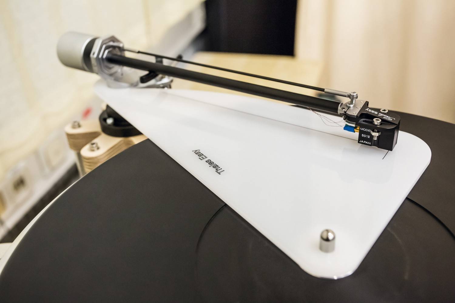
Frank is correct that the Thales diameter can be any length and since the guide arm is a fixed pivot we don't have to adhere to the Thales drawing. The B point can be "floating" and we can come up with a curve that works as a guide rail. Doug's picture is a good example. Thanks!
My own preference is to have the guide arm as short as possible to have the least skating force and I am beginning to believe skating force is worse than tracking error. I will trade zero skating force over zero tracking error. So if we can make point P as close to point B as possible that would be optimum.
So that funny figure I've been rattling on about is an ellipse. I seem to remember something about major and minor radii from high school drafting and I have a couple of friends with CNC milling machines. Maybe I can work something out.
DD - Thanks for straightening out who was asking about a 320 mm Thales diameter
and Jonathon - Thanks for running the numbers based on 320 mm. I learned a lot going through that table, especially about the importance of null points. Good luck with your project and I hope you'll be posting soon.
Everybody - It's been an interesting year and however you celebrate the last few days of it, I hope you're doing well and enjoying yourselves.
Hi Doug, directdriver, all: Been a little busy with year-end social responsibilities and preparations for the CES. My analysis of Doug's 320mm, 218mm, 39mm geometry has come to a halt at the mid-way stage, but I plan to finish this once the CES is over.
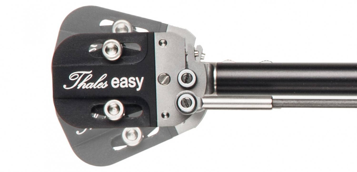
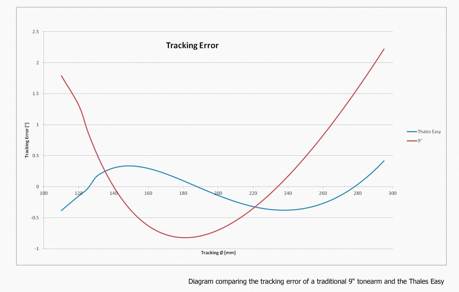
The tracking error graph of the Thales Easy tonearm that directdriver posted should be no surprise, and illustrates that, rather than being linear trackers in the strict sense of the term, these and Birch-type tonearms optimally have three-null geometry. Using Excel to convert the previously posted tracking error tables into linear graphs should show similar shapes.
Once we see start seeing graphs of the tracking errors (rather than number tables), it may be time to consider the impact of linear groove velocity on the tracking error audibility, and how to best choose the null radii. A simple way would be to prioritize the lowest error numbers (regardless of linear groove velocity), similar to the Baerwald philosophy of conventional two-null tonearms. A different way would be to weight the tracking error against the linear groove velocity so that the distortion that the ear hears is more consistent across the entire LP surface. This would be closer to the Stevenson philosophy (or as a less extreme approach, the recent Uni-DIN), and should push the three null radii closer to the LP label.
All of the above written under the assumption of a constant guide pivot B, rather than a floating B.
kind regards, jonathan
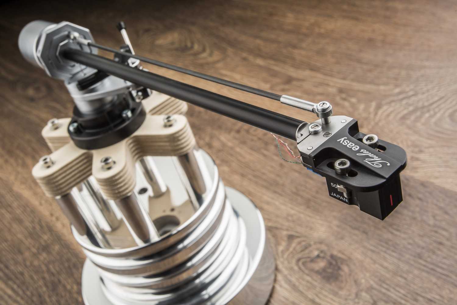
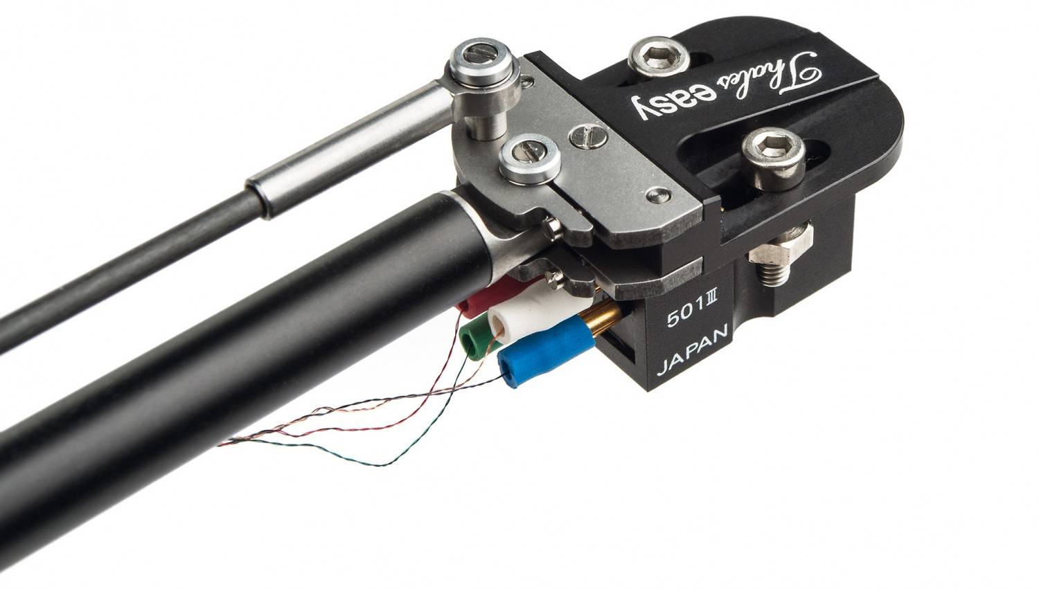
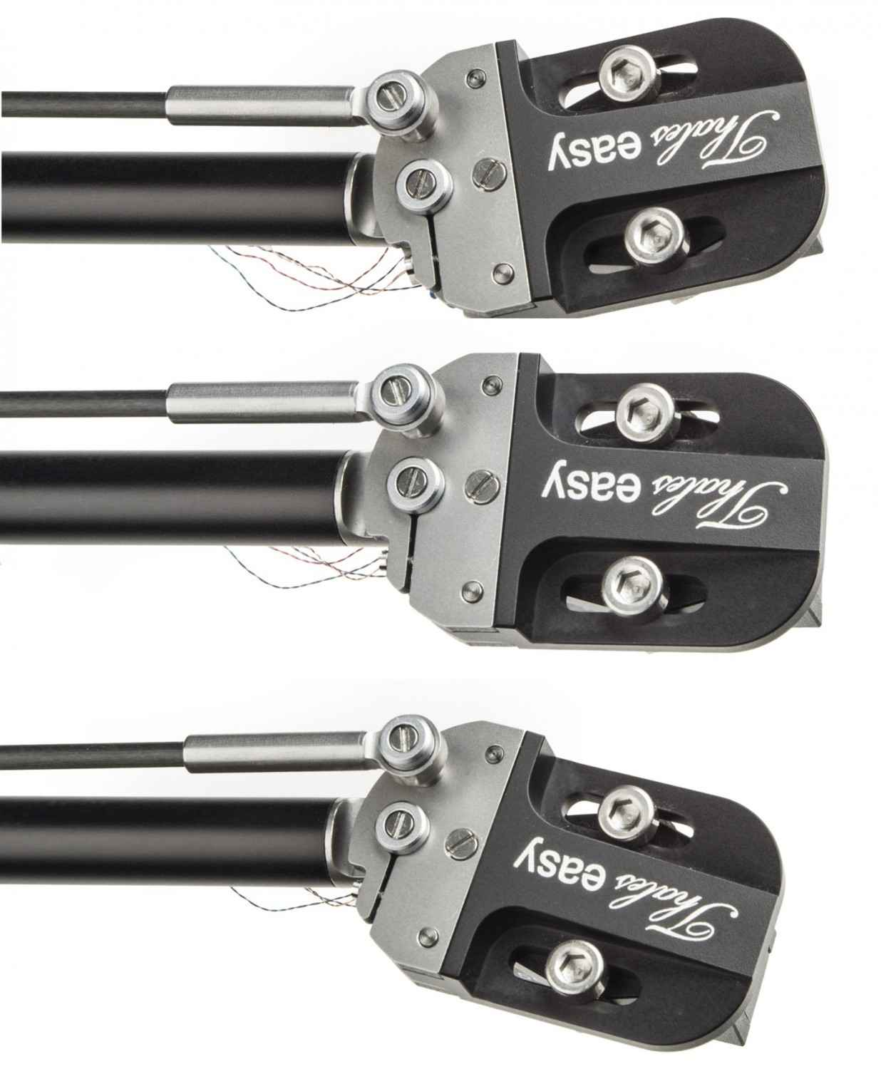
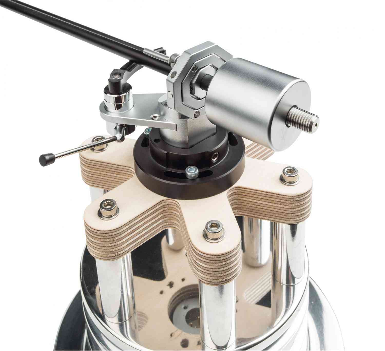
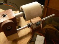
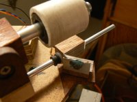
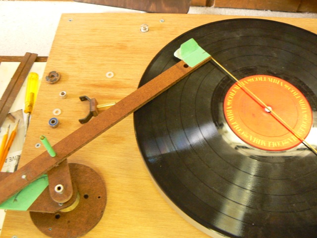
There's a mechanical problem with a long swing arm/short pivot arm Birch variation. The headshell is inherently rests uncomfortably close to the platter, but by splitting the guide into two hinged parts, the headshell can be moved farther away.
There is a small magnet - under all that blue tack - and a small attractor in the wooden part which keep the hinge closed during play.
Following jcarr's lead on the tracking ability of short arms renders this moot, but I just prefer longer arms and it was fun to figure out.
There is a small magnet - under all that blue tack - and a small attractor in the wooden part which keep the hinge closed during play.
Following jcarr's lead on the tracking ability of short arms renders this moot, but I just prefer longer arms and it was fun to figure out.
Attachments
Vertical effects of tonearm length.
Doug,
Your instincts are correct. Articles by Villchur and Pramanik in Audio magazine** showed the geometry involved, but basically the length question addresses warped vinyl records.
If the arm is short, its up/down motion from the warp leads to "warp-wow", a swooshing noise at a subsonic rate. It also periodically alters the orientation of the stylus in the groove (VTA experimenters, Alert!).
This is acutely noticed in warps played by straight-line-tracking players with short arms. It is not as bad as it once was thanks to record weights and vacuum hold-down players. However, the RCA switch to "Dynagroove" (cheap bendable vinyl) in the 1960s didn't help.
** A New Turntable-Arm Design, Edgar Villchur; Audio, September & October 1962. [online at vinylengine.com, I believe]
** Understanding Tonearms, S.K. Pramanik; Audio, June 1980. [can't find this online, but I have a copy....]
Andy
I own several test records that are keyed to Graphic Level Recorders (usually from General Radio), useful for plotting frequency response and channel separation. In the past, I used suitable wide range ac voltmeters, etc. and could make the plots manually from their readings.
Does anyone know of conversion programs that can take an analog preamp output and display it on a PC screen? I have seen some that use the internal A/D cards but only go to 20kHz so I don't know how accurate they are.
Andy
Does anyone know of conversion programs that can take an analog preamp output and display it on a PC screen? I have seen some that use the internal A/D cards but only go to 20kHz so I don't know how accurate they are.
Andy
I use Soundcard Oscilloscope with RME HDSP 9632. HDSP 9632 can do 192kHz. So, I have no problem to display signal over 20kHz. This is the link for Soundcard Oscilloscope.
Soundcard Scope
I also bought a Behriniger Phono to use with the sound card.
Soundcard Scope
I also bought a Behriniger Phono to use with the sound card.
I read the software manual again. Its sampling rate is 44.1 kHz and 16 bits. So, the highest frequency the software can do is 20kHz. It was my mistake.
However, the sound card is capable of sampling up to 24 bit and 192 kHz. I have used Adobe Audition to record LP way up to 40kHz and above.
However, the sound card is capable of sampling up to 24 bit and 192 kHz. I have used Adobe Audition to record LP way up to 40kHz and above.
Jim,
I made a wrong assumption, then. To me, Behringer Phono (a solid-state preamp, PP400) + A/D converter meant something else. As I first stated, I was looking for a less labor-intensive way of plotting cartridge response and separation. Your comments were helpful. I just hoped we WERE on the same page.
Andy
Last edited:
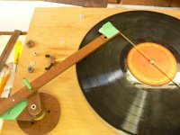
quasi-Van Eps
Interesting experimental Van Eps style articulated tonearm.
https://www.youtube.com/watch?v=N_DjmJwevj8
Interesting experimental Van Eps style articulated tonearm.
https://www.youtube.com/watch?v=N_DjmJwevj8
- Home
- Source & Line
- Analogue Source
- Angling for 90° - tangential pivot tonearms