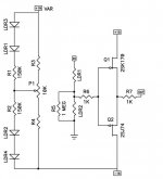
OK, this would be the last manual version that you are
likely to see. It has all the pieces, and allows pretty complete
adjustment of input impedance and range, top to bottom.
As a 2 channel piece, LDR1 and LDR3 should be matched to
each other, and LDR2 and LDR4 should also be matched.
The match should take place around the 5 Kohm resistance
value. LDR1 and 3 do not have to match LDR2 and 4.
Attachments
I thing this Lightspeed version has too less attenuation (-40dB) when you put the powerful JFETBOZ (+22 dB) behind it!
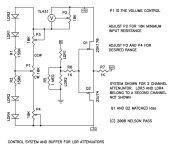
Stereo LDR Circuit with Buffers
As posted by Mr. Pass here's the stereo circuit in detail. Let me know if I missed something...😎
Nelson Pass said:OK, this would be the last manual version that you are
likely to see. It has all the pieces, and allows pretty complete
adjustment of input impedance and range, top to bottom.
As a 2 channel piece, LDR1 and LDR3 should be matched to
each other, and LDR2 and LDR4 should also be matched.
The match should take place around the 5 Kohm resistance
value. LDR1 and 3 do not have to match LDR2 and 4.
As posted by Mr. Pass here's the stereo circuit in detail. Let me know if I missed something...😎
Attachments
Tolu said:I thing this Lightspeed version has too less attenuation (-40dB) when you put the powerful JFETBOZ (+22 dB) behind it!
I deliberately chose -40 dB because the tracking was still pretty
good. In the lastest version, you can adjust the range pots to
get down to -70 or -80 dB if you want.
And of course you can have less gain in the JFETBOZ without
any difficulty.
jboz buffer
Nelson,
Newbie question.........
What if I don't want any gain from the jboz. I just want the connection as follow:
" CD - Lightspeed with buffer - poweramp with 12k input."
I thought I'll need a buffer with 600R to 1K output, am I right?
Many thanks
Albert
Nelson,
Newbie question.........
What if I don't want any gain from the jboz. I just want the connection as follow:
" CD - Lightspeed with buffer - poweramp with 12k input."
I thought I'll need a buffer with 600R to 1K output, am I right?
Many thanks
Albert
Hi,
your proposed buffer could have an output impedance of around 1ohm.
Just add a series resistor to make it tolerant of shorting the output.
100r would usually do.
your proposed buffer could have an output impedance of around 1ohm.
Just add a series resistor to make it tolerant of shorting the output.
100r would usually do.
Re: jboz buffer
It's not important. I suggest you use the one in a TO-92 type
package, as the surface mount ones are difficult to work with.
If by this you mean the 1K resistor already at the output of the
buffer, you'll be fine. You can play with other values, but at some
arbitrarily low resistance the circuits become prone to oscillatory
interactions with the load.
Harry3 said:As there are a number of TL431 types available, what is the prefered version?
Thanks
It's not important. I suggest you use the one in a TO-92 type
package, as the surface mount ones are difficult to work with.
albertli said:nt any gain from the jboz. I just want the connection as follow:
" CD - Lightspeed with buffer - poweramp with 12k input."
I thought I'll need a buffer with 600R to 1K output, am I right?
If by this you mean the 1K resistor already at the output of the
buffer, you'll be fine. You can play with other values, but at some
arbitrarily low resistance the circuits become prone to oscillatory
interactions with the load.
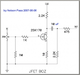
That's where I've seen this buffer before, Pioneer used it as well on the rear end of their top shelf "Stable Platter" cd players like my old PD-77 PD-75, they wanted to keep the poor old NE5532 isolated from the outside world, so they buffered it with this Fet buffer. But they kept it within the feedback loop, and they also used a NP "Nelson Pass" 🙄 coupling cap.
Cheers George
Cheers George
Attachments

So what do you guys think is the best option for me?
I have a sony cdp x3000es going straight to an old old marantz 300dc power amp which I think is only 33k input impedance.
My question is which option should i go for/be best suited to my setup? the standard lightspeed clone or the buffer version???
also the power amp has dual pots for tuning each channel does this mean i wont have to match the ldr's ?
Hi, the pots have to go, this is the whole reason behind the Lightspeed.
The easiest/best way is to sub the 33k resistor for say 68k and bypass the pots in the Marantz, but never power up the Marantz without the Lightspeed or another preamp attached, just in case it's a bi-polar input amp and not Fet.
Or do the buffer after the Lightspeed and just bypass the pots in the Marantz which will be a compromise compared to the first option, but still better than any other way.
Cheers George
Nelson Pass said:
Hi, I'm late for this thread, may I ask a stupid question?
Are those 2 resistors of 150k (R1 & R2) there for reducing the current on the LDR's string, and making the voltage divisions by the VR string significant enough?
But, they also significantly reduce the voltage and current seen by the LDR's, wouldn't they?
So, the LDR's would never fully turned on, and there'd always be some degree of attenuation even if the VR is turned fully CW.
If I need this without the "buffer" stage, how can I modify the circuit?
Thanks a lot🙂
NSL-32RS2S optocouplers
Hi friends,
I just get received the package from Allied Electronics included ordered NSL-32SR2S Silonex optocouplers. I just see in the box 3 different types of ordered optocouplers !?. I clearly see on the body of each one following printed numbers & letters : "387 R2C" and "307 R2E and R2G". On the www of AE are on the attached photo "364" numbers. Did they sent to me proper optocouplers ?
Hi Krzysztof, just try to make both channels of the series the same letter and the same for both channels of the shunt, this will give you the closest resistance match, the number is just a batch number. See spec sheet attached.
You will still have to hand match the pairs, there is no free lunch when building the Lightspeed Attenuator.
You have to take the pain to enjoy the gain.
BTW don't forget to vote for a Passive Preamp forum here.
http://www.diyaudio.com/request/
Cheers George
You will still have to hand match the pairs, there is no free lunch when building the Lightspeed Attenuator.
You have to take the pain to enjoy the gain.
BTW don't forget to vote for a Passive Preamp forum here.
http://www.diyaudio.com/request/
Cheers George
Attachments
sorted optocouplers
Hi George,
Thanks for reply. I paid for SORTED NSL-32RS2S optocouplers. Do you use in commercial Light Speed peamplifier sorted optocouplers with printed "364" letters on the body of each one ?. I`m not sure Allied sent to me proper optocouplers. On the below link you can see seventeen types of NSL optocouplers http://www1.silonex.com/audiohm/index.html
Please also look here : http://www.alliedelec.com/Search/Pr...SR2S&R=6993011&SEARCH=6993011&DESC=NSL-32SR2S
Like I said the 364 is just a batch no. I know bought and paid for sorted ones, but you still have to match them, remember no free lunch.
Cheers George
Cheers George
matching
Hi again George,
Thanks once more for explanation. I just see on each optocoupler two pieces of long leads and two short ones and additionally white point on the body of each optocoupler. Do the long leads are inputs ?. Do the white point means cathode of LED ?
Hi again George,
Thanks once more for explanation. I just see on each optocoupler two pieces of long leads and two short ones and additionally white point on the body of each optocoupler. Do the long leads are inputs ?. Do the white point means cathode of LED ?
- Home
- Source & Line
- Analog Line Level
- Lightspeed Attenuator a new passive preamp