samoloko,
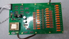
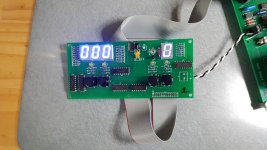
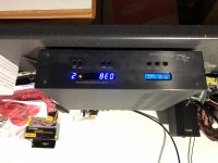
Here are pictures of the three boards installed and operating properly. Note that the main board is attached to the display board with a ribbon cable. The display boards power connector and ribbon cable header are both soldered to the back of the display board, which is designed to be attached to the front panel. The controls will not operate if the ribbon header in attached to the top of the display board. Also note the initial position of the display at startup. Volume is "000" and no input is selected "0". The red mute light that will turn on if the mute control is pressed. Also, the display board's blue LED will light when a remote control is pressed.
If the ribbon cable is correctly made there should not be any consistent relay clicks when the main board is powered up. I will still get a few clicks occasionally on power up, but they are fairly rare. When building the boards I would first test that the buttons on the display board are operating correctly before testing the remote. If the display board controls are working correctly but the remote control has problems it is most likely the surface mount chip on either the display board or the remote.
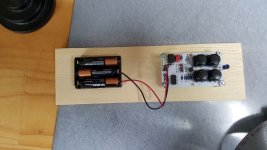
You will notice that I just "boarded" the remote control and turn it on or off by pulling the battery connection. If you plan on building the remote control you should include the suggested on-off switch. If you run into problems during the build you should read (if you haven't already) the discussion John and I had on debugging procedures earlier in the thread.
Here are pictures of the three boards installed and operating properly. Note that the main board is attached to the display board with a ribbon cable. The display boards power connector and ribbon cable header are both soldered to the back of the display board, which is designed to be attached to the front panel. The controls will not operate if the ribbon header in attached to the top of the display board. Also note the initial position of the display at startup. Volume is "000" and no input is selected "0". The red mute light that will turn on if the mute control is pressed. Also, the display board's blue LED will light when a remote control is pressed.
If the ribbon cable is correctly made there should not be any consistent relay clicks when the main board is powered up. I will still get a few clicks occasionally on power up, but they are fairly rare. When building the boards I would first test that the buttons on the display board are operating correctly before testing the remote. If the display board controls are working correctly but the remote control has problems it is most likely the surface mount chip on either the display board or the remote.
You will notice that I just "boarded" the remote control and turn it on or off by pulling the battery connection. If you plan on building the remote control you should include the suggested on-off switch. If you run into problems during the build you should read (if you haven't already) the discussion John and I had on debugging procedures earlier in the thread.
Attachments
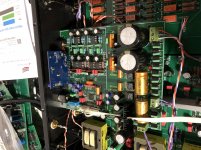
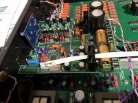
And adding pics of my preamp. Inside the preamp the board on the left is the gain stage line preamp, fully balanced, on the right is the control board, and the little board mounted to the upper back of the chassis is the DAC.
Looks at the very dusty faceplate you can see the preamp controls on the right and the DAC controls on the left.
Looks at the very dusty faceplate you can see the preamp controls on the right and the DAC controls on the left.
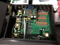
Don't know if I ever mentioned it but you can get the seven segment LEDs in Red, Yellow, Green and other colors. The Blue is of course the most expensive, the Green the least expensive. You can save $12 by using the Green LEDs, which is what I did for some test boards so I didn't have to unsolder the 10 pin devices, although with the Metcal soldering station you can see behind the preamp I have a tip to do all ten pins at once and the chip just drops out. Good tools and niiiiiiiice.
Just come across this project, and note you describe the attenuator as an R2R ladder - its not, its a binary weighted switched attenuator. R2R ladders have only two values of resistor, R and 2R, and their input impedance is very non-constant, which would mandate an input buffer. R-2R ladder has a constant output impedance though.
I notice a worrying lack of decoupling caps for the logic chips - you need 100nF ceramic per chip to guarantee stable operation.
I note also the wise choice of a 7555 CMOS version of the 555. The original 555 is horrendously noisy to its supply rails.
The dilemma about attenuate before or after preamp gain stage can be finessed by using the attenuator as the negative feedback network in the gain stage itself, meaning the optimal noise and headroom can both be achieved. The rules of "don't attenuate then amplify" and "don't amplify then attenuate" can both be assuaged.
Hi Mark,
You are correct about the attenuator not being a R2R ladder, I changed the design at the beginning to the current resistor values since I liked my Pass Preamp.
The design has few chips operating at the same time and with 2000 uf in the power supply the design is stable. I tried putting a .1 uf ceramic cap across the chips in the prototype and saw no difference with or without.
The attenuator was designed to work with another gain stage already built so a variable gain stage wasn't an option, though I like the idea, like the Pass preamp.
But I appreciate your reading the post and giving your feedback.
Lack of decoupling can lead to many different symptoms, that come and go, are pattern sensitive, and basically are a right pain. 0.1uF caps are cheaper than cheap, just use them without thinking about it in any digital system and you won't get caught out when you least expect it!
The issues with missing decoupling happen on a timescale of a nanosecond or so, the 2000uF power supply cap isn't even visible at such timescales. In fact every wire is much more of an inductor than a resistor at these timescales - we talking 4 or 5 orders of magnitude faster than audio signals.
The issues with missing decoupling happen on a timescale of a nanosecond or so, the 2000uF power supply cap isn't even visible at such timescales. In fact every wire is much more of an inductor than a resistor at these timescales - we talking 4 or 5 orders of magnitude faster than audio signals.
Here are the updated Gerbers with decoupling caps across the Main and Display Board.
All boards gerbers and schematics and BOM are attached for completeness.
All boards gerbers and schematics and BOM are attached for completeness.
Attachments
the last post lost the pics.
Hi John, what are the yellow cap in this pic?? Jensen??
Thanks John, when you have a change, no rush, could you take a close pic..thanksHi Hicoco,
If you are referring to the Gold caps on the small DAC board the only name I find on them is RUE. The DAC is a purchased board so I do not have a BOM for it.
Thanks,
John
Just come across this project, and note you describe the attenuator as an R2R ladder - its not, its a binary weighted switched attenuator. R2R ladders have only two values of resistor, R and 2R, and their input impedance is very non-constant, which would mandate an input buffer. R-2R ladder has a constant output impedance though.
I notice a worrying lack of decoupling caps for the logic chips - you need 100nF ceramic per chip to guarantee stable operation.
I note also the wise choice of a 7555 CMOS version of the 555. The original 555 is horrendously noisy to its supply rails.
The dilemma about attenuate before or after preamp gain stage can be finessed by using the attenuator as the negative feedback network in the gain stage itself, meaning the optimal noise and headroom can both be achieved. The rules of "don't attenuate then amplify" and "don't amplify then attenuate" can both be assuaged.
So if you read the first post a little closer you will see that the board I was evaluating, the one with problems, had an R2R resistor ladder not my board design.
Ran into a situation with a user with hi-output source, high gain amp and sensitive loudspeakers, and was only able to use the first 60 steps of the 256 on the volume control. So some alternate resistor values were needed.
The current resistors are:
8K 4K 2K 1K 500R 250R 125R 62R
new values
20K 10K 4.99K 2.55K 1.24K 619R 316R 162R
so if anyone has the same issue you can try these values. These are standard values in Vishay Dale RN65 and RN70 series. Looked at Caddock from Mouser and they only has the first three values and they are rather expensive so I only considered them for about three seconds.")
The current resistors are:
8K 4K 2K 1K 500R 250R 125R 62R
new values
20K 10K 4.99K 2.55K 1.24K 619R 316R 162R
so if anyone has the same issue you can try these values. These are standard values in Vishay Dale RN65 and RN70 series. Looked at Caddock from Mouser and they only has the first three values and they are rather expensive so I only considered them for about three seconds.
Another set of alternate values for those who already have the current resistors you can re-use them by moving them down one and buying one new value for the largest.
The current resistors are:
8K 4K 2K 1K 500R 250R 125R 62R
new values
16k 8K 4K 2K 1K 500R 250R 125R
20K 10K 4.99K 2.55K 1.24K 619R 316R 162R
Attached is an updated BOM
The current resistors are:
8K 4K 2K 1K 500R 250R 125R 62R
new values
16k 8K 4K 2K 1K 500R 250R 125R
20K 10K 4.99K 2.55K 1.24K 619R 316R 162R
Attached is an updated BOM
Attachments
So for over two months I have had the new resistors for the volume section and the new remote receiver and transmitter boards built and tested but can't seem to find time to install them in the preamp. With building the new house with dedicated sound room and now having to rebuild my work truck engine I am strapped for time. Hopefully in four or five months I can get back to audio, my toys and passion, so I can sit an listen to some of my vinyl just for the joy of the music.
Sorry for the rant, just blowing off my frustration, everything seems to get it the way of just listening to the music.
Sorry for the rant, just blowing off my frustration, everything seems to get it the way of just listening to the music.
- Home
- Source & Line
- Analog Line Level
- Preamp Control - Volume, input, mute, remote