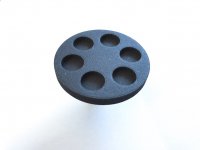
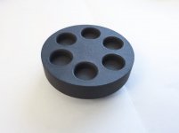
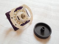
This was my prototype knob ordered from Shapeways in Black Natural Versatile Plastic. This cost about 12 EUR.
I love Shapeways, it's such a great service. There's definitely cheaper services but the finishing quality usually worse in my experience.
I love Shapeways, it's such a great service. There's definitely cheaper services but the finishing quality usually worse in my experience.
Attachments
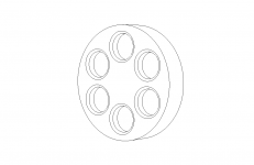
This is my final knob design.
You can see a 3d render of the STL file here: preamp-two/knob.stl at master * FutureSharks/preamp-two * GitHub
This was ordered in Shapeways Black Premium Versatile Plastic and cost about 26 EUR per piece. It's a much smoother finish than the prototype but obviously more expensive
You can see a 3d render of the STL file here: preamp-two/knob.stl at master * FutureSharks/preamp-two * GitHub
This was ordered in Shapeways Black Premium Versatile Plastic and cost about 26 EUR per piece. It's a much smoother finish than the prototype but obviously more expensive
Attachments
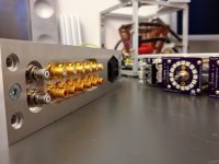
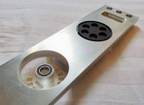
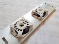
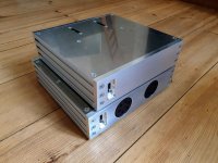
I had a problem where the 3d printed knob would not rotate perfectly straight when mounted onto the encoder. So I designed a bracket to hold the PCB, encoder, a 6800 bearing and the knob all together in one unit. The knob press fits into the bearing. Now it turns completely straight. Even when pressed with force.
The bracket was also printed by Shapeways.
The bracket was also printed by Shapeways.
Attachments
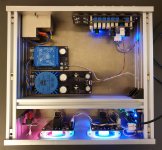
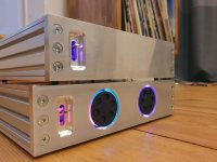
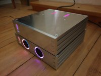
OK I think I'm done! It's been running great for over a week now. Really surprised at how silent it is. I was expecting to have some grounding issues or some other annoying fault but it seems to run perfect. Phew.
Quite a long project I guess. This thread was started 3 years ago but the design is based on my last preamp project and work done in this thread from 2013.
Here's a GIF of it working: Animated GIF - Find & Share on GIPHY
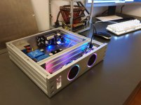
Python code, photos, CAD files, PCBs, schematics and more are all here: GitHub - FutureSharks/preamp-two: An digitally controlled hi fi preamplifier 🔈🎵
Quite a long project I guess. This thread was started 3 years ago but the design is based on my last preamp project and work done in this thread from 2013.
Here's a GIF of it working: Animated GIF - Find & Share on GIPHY
Python code, photos, CAD files, PCBs, schematics and more are all here: GitHub - FutureSharks/preamp-two: An digitally controlled hi fi preamplifier 🔈🎵
Attachments
that chip looks really good. Arduino control is great. My setup is not well suited as I am using a twin triode 6922 setup with the first stage driving the 100k pot with loudness function. The second 6922 drives the tone stack which then drives the SS amp.
Great looking preamp!!
input LEDS or LCD in the centre of wheel would indicate which input is selected and volume level expressed as -Db
Great looking preamp!!
input LEDS or LCD in the centre of wheel would indicate which input is selected and volume level expressed as -Db
Last edited:
Hi Max, again pretty nice project. I'm about to request the BOM to complete the input selector board, and have a (stupid) question.
I understand the MCP23S17 serves as a SPI expander, so we can use the SPI line between an Arduino and more than one sensor or IC.
What I'm not so clear about is the ULN2003V12DR relay load drivers. Since these support 3.3V to 5V CMOS logic input interface, wouldn't it be possible to send those signals from the MCP23S17 or Arduino directly? I mean, the latching relays just need a pulse, right?
Sorry, I know these are stupid questions, but would love to learn more.
Thank you
Sorry, I know these are stupid questions, but would love to learn more.
No such thing
")
I understand the MCP23S17 serves as a SPI expander, so we can use the SPI line between an Arduino and more than one sensor or IC.
Correct.
What I'm not so clear about is the ULN2003V12DR relay load drivers. Since these support 3.3V to 5V CMOS logic input interface, wouldn't it be possible to send those signals from the MCP23S17
To quote the datasheet:
> Internal Free-Wheeling Diodes for Inductive Kick-Back Protection
If you don't have these then you will need a diode across each relay coil.
or Arduino directly? I mean, the latching relays just need a pulse, right?
Sure but then you need many free pins on the micro controller. 2 per relay. And depending on what controller you are using, you might not have that many free pins. That's why IMO it's nicer to use SPI.
coolNo such thing
OK, I wasn't conceptually far, then!Correct.
To quote the datasheet:
> Internal Free-Wheeling Diodes for Inductive Kick-Back Protection
If you don't have these then you will need a diode across each relay coil.
Sure but then you need many free pins on the micro controller. 2 per relay. And depending on what controller you are using, you might not have that many free pins. That's why IMO it's nicer to use SPI.
Now, a not-stupid, just maybe weird scenario/question. Would it be possible to use the input selector to switch audio signals and also close/open power circuits? Changing the arduino code, maybe even changing the pcb design, that is. Example situation: relay 1 for phono audio, relay 2 for phono amp power circuit, relay 3 for dac audio, relay 4 for dac power circuit, relay 5 for aux audio. If this is conceptually possible, i would be able to only power the phone amp or the dac when i select those specific audio signals
As for the last question, maybe if switching power circuits is not supported by this design (even if modified), then I need to look into "triggers", i.e. Signal Detecting Auto Power-On Unit (project 38) by Rod Elliott (ESP), but will obviously do some more research.
Would it be possible to use the input selector to switch audio signals and also close/open power circuits?
It won't work as it's designed as (6 input, 1 output) x2. Perhaps you could have voltage going in and then you can connect 6 devices to this bus. It might work for low voltage things but definitely not safe for mains voltage.
Personally I would look for another solution. You can get cheap relays that you can control with an Arduino from Aliexpess.
I think I'll keep the original use for the relays. Is it safe to leave 2 or 3 relays unpopulated?It won't work as it's designed as (6 input, 1 output) x2. Perhaps you could have voltage going in and then you can connect 6 devices to this bus. It might work for low voltage things but definitely not safe for mains voltage.
Hadn't thought of cheap relays, it's a nice idea. Thank youPersonally I would look for another solution. You can get cheap relays that you can control with an Arduino from Aliexpess.
Is it safe to leave 2 or 3 relays unpopulated?
Sure
- Home
- Source & Line
- Analog Line Level
- My new preamp design: Arduino, 6 input selector, MDAC attenuator, IR etc