") . The third is for the muses volume attenuator and input selector board.
. The third is for the muses volume attenuator and input selector board.Should work for heat exchanger in this kind of project. I also vote arrangement option 3.It is an enclosure from Ali, 3mm aluminium throughout except the front face. 60mm headroom.
I think I will use an aluminium angle as a heatsink, bonded to the floor or side + thermal grease and screws.
Iconic gauge wrapped British toroids there by the way. Custom Tiger 🐅 ?
Hi Salas,
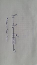
Based on BOM & previous posting :Dc Db Da LEDS drop the rail voltage to 12V relay safe working range territory. One of them can be actually brought to the front panel as "ready" sign because they light up only when the relay clicks. You could introduce a switch in the three LEDs chain cutting power to the relay using it as a mute function control. Post #5654/Page283.
Can you confirm the attached drawing. By doing this, I am cutting power to the Mosfet, yes? Thanks.
Attachments
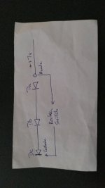
No don't do that. Solder two wires in the board pads instead of populating one of those LEDs. Bring the anode pad wire to a single pole mini toggle switch installed at the panel. In series to it connect a panel LED's anode. Solder the other wire to its cathode.
In that way when the switch is on the delay circuit is online and the panel LED lights up after a few seconds delay at power on. Indicating when signal output is ready.
When the switch is off the delay circuit goes offline and the signal output disengages. Its essentially a mute position. Signal output means both line and headphones.
Hi Salas
apologize in advance, I need more/precise instructions as I am new to this.
"Solder two wires in the board pads" where on the DCG3 board?
"Bring the anode pad wire to a single pole mini rocker switch installed at the panel. In series to it connect a panel LED's anode. Solder the other wire to its cathode." You mean like the attached drawing. I am sure that my interpretation is wrong.
Attachments
To add tape loop you need a monitor input switch. That avoids signal loopback chaos when monitoring with a three head machine.I would like to have a tape loop on my DCG3, what’s the most straightforward way to do this -
Meaning a further input to a switch choosing between the I-Select's output and that input. From that switch you route to the volume pot. Also needing a REC out tap from the I-select's output before that monitor switch. You set the I-Select to what input you want to record from. You use the monitor input for listening to the real time tape recording or for listening to tapes replay in general.
...Hi Salas
apologize in advance, I need more/precise instructions as I am new to this.
"Solder two wires in the board pads" where on the DCG3 board?
"Bring the anode pad wire to a single pole mini rocker switch installed at the panel. In series to it connect a panel LED's anode. Solder the other wire to its cathode." You mean like the attached drawing. I am sure that my interpretation is wrong.
Got it Salas. Based on your drawing, you remove Da LED & placed it on the front panel. The 2 wires are from the Da holes on the board. Ok, thanks for clearing that up. Do all red LED have the same voltage drop as I might need to buy a new one. BTW I just received the pf5102 from Tea and I shall work on my bad DCSTB later this week. Will keep you posted.
Started with my DCG3 building, after having the parts sitting in a box for a couple of years. Finished with the resistors soldering in DCG3 and DCSTB boards. Almost. Seems that the four Rb1, Rb2 (3.3k) are missing from my DSTB full kits, but there are four extra 1Ohm resistors instead. What wattage rating should I use for the 3.3k Rb1, Rb2? Should these be low ppm as well?
Just an update for Salas. I got the replacement PF5102 from Tea yesterday and it resolve the B+ voltage problem. I think the J1 was bad from the day I installed it. I can't help to think it was damaged in transit (static discharge or X-ray inspection by custom -they do that randomly for drugs). From past reading on the 300+ pages, I found the transistors on the DSCTB are quite sensitive and prone to damage.
Anyway this is the loaded dc output voltage: board 1 ( pf5102 fix) = -17.42/+17.55; board 2 = -17.6/+17.57. Salas, is this a little high? I see most fellow builders are having 17.2 average.
After adjusting dc bias, I put the Raven CD by Rebecca Pidgeon. I use a variable output Dac and listen through a pair of AKG can. It was rich and full body, very musical. This is a not my favorite CD and somehow I want to hear more. There were some hum in the background. but the whole thing from transformer to the preamp is laying out in the open and I am using unshielded & crappy wire for connection. So I am not concern at this stage. I think I will order/build a second DCG3 board from Tea cause I like it a lot, it has high SQ and flexibility in terms of gain adjustment and impedance. Once again thank you Salas for sharing.
To add tape loop you need a monitor input switch. That avoids signal loopback chaos when monitoring with a three head machine.
Meaning a further input to a switch choosing between the I-Select's output and that input. From that switch you route to the volume pot. Also needing a REC out tap from the I-select's output before that monitor switch. You set the I-Select to what input you want to record from. You use the monitor input for listening to the real time tape recording or for listening to tapes replay in general.
Hmm, might be simpler to buy a pre amp with a tape loop and swap it in place of DCG3 when I want to record something. Has anyone installed a tape look in their DCG3?
@luckydork
Congratulations for fixing the issues. Your B+/B- lines are still within accepted limits, no worries. Nice to know its also subjectively appelaling to you already. Will be even better when finished. You are welcome, and keep us posted.
Congratulations for fixing the issues. Your B+/B- lines are still within accepted limits, no worries. Nice to know its also subjectively appelaling to you already. Will be even better when finished. You are welcome, and keep us posted.
Not anyone that I remember showing such an addition in this thread.Hmm, might be simpler to buy a pre amp with a tape loop and swap it in place of DCG3 when I want to record something. Has anyone installed a tape look in their DCG3?
- Home
- Source & Line
- Analog Line Level
- Salas DCG3 preamp (line & headphone)